NORD Drivesystems BU0260 User Manual
Page 41
4 Commissioning
BU 0260 GB
Subject to technical amendments
41
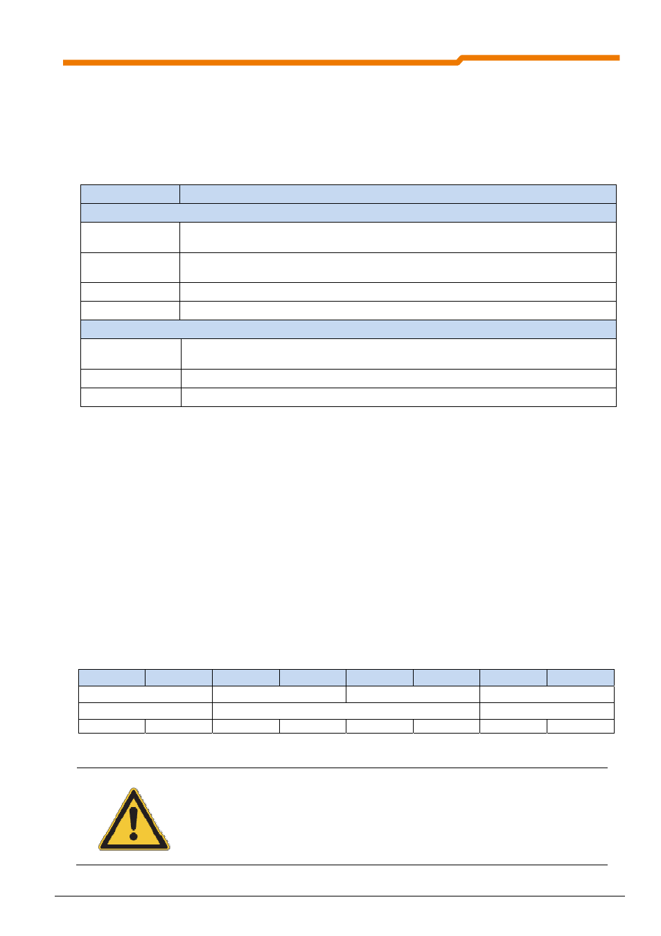
4.5.2.2 PDO operating modes (transmission type)
The "transmission type" determines when a transmit PDO is transmitted and when the data from a receive
PDO is processed (see also Section 8.3.2.1 "PDO (Process Data Object)"). These settings are made in
parameter (P162) (and therefore in objects 0x1400-0x1404 Sub. 2 for Rx -PDOs or 0x1800-0x1804 Sub. 2 for
Tx -PDOs). The following settings can be made with NORDAC frequency inverters:
Transmission type Value
Transmit PDO (Tx)
0
PDO is transmitted if a SYNC command has been received and the data (status) has changed
since the last SYNC command.
1-240
PDO is transmitted if 1..240 SYNC commands have been received, whether the data (status)
has changed or not.
252-253
Reserved
254, 255
PDO is transmitted immediately if the data (status) has changed (standard setting).
Receive PDO (Rx)
0-240
Data from the Receive PDO is only processed after the next SYNC command has been
received.
252-253
Reserved
254, 255
Data from Receive PDO is processed immediately (standard setting)
4.5.2.3 Inhibit time
For each Transmit PDO an individual "Inhibit time" can be defined in (P163) (and therefore in objects 0x1800-
0x1804 Sub. 3). This can be used to set a minimum transmission interval between two PDO messages. In
networks with a large number of participants, the bus load can be influenced with this value. The standard
setting is 10ms.
4.5.2.4 Event time
The Parameter "Event time" (P164) (and therefore objects 0x1800 – 0x1803 Subindex 5) can be used for all
Transmit PDOs. Cyclical transmission of the PDOs is achieved via this value. The standard setting is 250ms.
4.5.2.5 PDO mapping
The sequence of the process data (PZD) in the PDOs is defined by the PDO mapping in parameter (P165)
(and therefore in the objects 0x1600 - 0x1604 or 0x1A00 - 0x1A04). Changes to the PDO mapping are only
permissible in the "Pre-Operational" state. The PDOs shown here correspond to the default setting.
Bit 0
Bit 1
Bit 2
Bit 3
Bit 4
Bit 5
Bit 6
Bit 7
Control word
Setpoint 1
Setpoint 2
Setpoint 3
16 bit
32 bit (e.g. position setpoint)
16 bit
Low byte
High byte
Low Low byte
Low High byte
High Low byte
High High byte
Low byte
High byte
The 16 and 32 bit process data must be transmitted in "Little Endian" format (Low byte - High byte).
NOTE
The PDO structure for a frequency inverter is pre-defined. With the use of the associated
EDS file, no adaptation for the exchange of data is necessary.
Due to mapping of the PDO with 16 bit width, so-called dummy mapping is not necessary.