2 rj12 diagnostic socket – NORD Drivesystems BU0260 User Manual
Page 34
Supplementary Manual CANopen for NORDAC SK 20E
34
Subject to technical amendments
BU 0260 GB
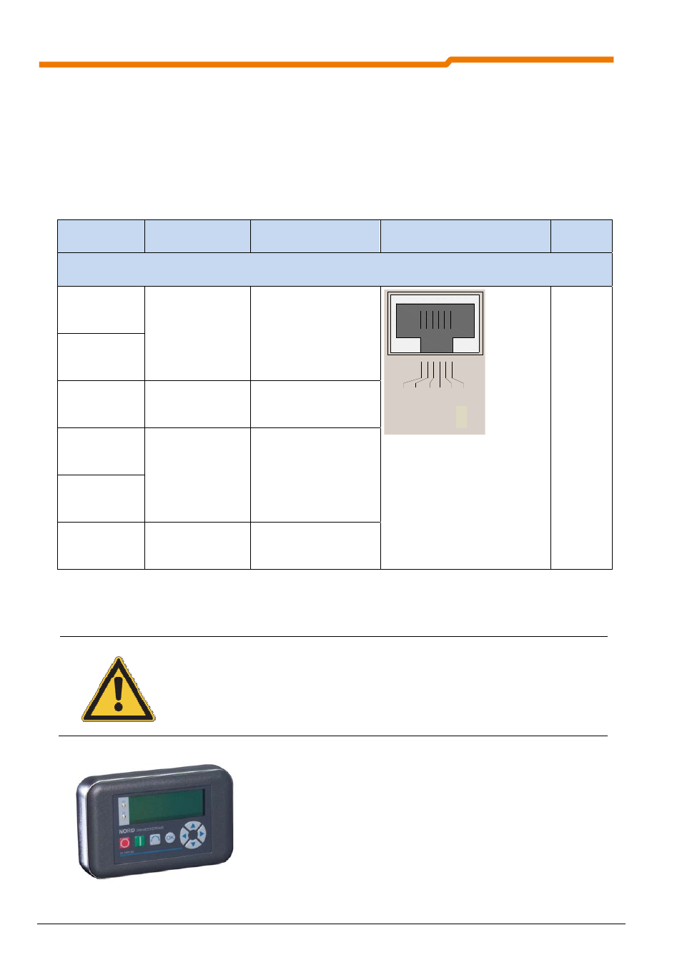
3.2 RJ12 Diagnostic socket
All participants which are coupled via a common system bus (field bus module / frequency inverter (up to 4
devices)) can be read out and edited/parameterised via an RJ12 diagnostic socket. This can be either the
diagnostic socket of the frequency inverter or that of the BUS connection units. This provides users with a
convenient facility to perform diagnosis and parameterisation from a central point, without having to access the
particular frequency inverter at its location.
Although the customer unit SK CU4-CAO does not have an RJ12 connection, it can be accessed from any
other subscriber (frequency inverter) on the same system bus.
Terminal/
Designation
Function
Data
Description / wiring suggestion
Parameter
Diagnostic access / RJ12, RS485/RS232
1 RS485
A
Data cable RS485
Baud rate
9600…38400Baud
Termination
resistor R=120
to be set by customer at
the final subscriber.
RS
48
5_
A
RS
48
5_
B
GN
D
TX
D
RX
D
+5
V
+2
4
V
RJ12: Pin No. 1 … 6
1: RS485_A
2: RS485_B
3: GND
4: RS232_TxD
5: RS232_RxD
6: +24V
P502
...P513
2 RS485
B
3 GND
Reference potential
for BUS signals
0V digital
4 232
TXD
Data cable RS232
Baud rate
9600…38400Baud
5 232
RXD
6 +24V
24V voltage supply
from FI
24V
20%
The bus speed of the diagnostic interface is 38400 baud. Communication is carried out according to the USS
protocol.
NOTE
Simultaneous use of several diagnostic sockets with several diagnostic tools may lead to
errors during communication. Therefore, only one diagnostic socket within a system bus
network should be used.
The ParameterBox SK PAR-3H is available as a diagnostic tool.
The necessary connecting cables are included in the scope of
delivery of the ParameterBox. For a detailed description of use,
please refer to Manual BU0040.
ParameterBox SK PAR-3H