NORD Drivesystems BU0260 User Manual
Page 83
7 CANopen Data transfer
BU 0260 GB
Subject to technical amendments
83
ATTENTION
If parameter changes are made, care must be taken that the maximum number of
permissible writing cycles to the frequency inverter EEPROM (100,000 cycles) is not
exceeded. I.e. continuous cyclical writing must be prevented.
For certain applications it is sufficient if the values are only saved in the RAM memory of the
frequency inverter. The corresponding setting is made via parameter (P560) "Save in
EEPROM".
Note: This does not apply to parameters which relate to the bus module ((P150) to (P199)).
Here too, the EEPROM only permits a maximum of 100,000 writing cycles. However, the
parameters are only written into the EEPROM if access is made via the ParameterBox or
NORDCON, or if the parameter values are changed in the bus module by means of SDOs.
7.2.1
Process data (PZD) in USS standard
In the process data area PZD, control words and setpoints or status words and actual values are transferred
from one node (frequency inverter) to another. The structure of the PZD area is always the same with regard to
the sequence of its elements (words (= 2 bytes each)) whereby the processing of the individual bytes is carried
out by the typical CAN method according to the "Little Endian" format.
The process data area of the reference data has the following structure:
- STW:
Control Word; length 16 bit, order telegram contains control bits (e.g. enable, rapid stop, error
acknowledgement)
- ZSW: Status Word; length 16 bit, response telegram contains status bits (e.g. FI running, fault)
- SW1..3: Setpoints; maximum 3 possible, 16 or 32 bit, order telegram
e.g. frequency setpoint, position setpoint, torque setpoint
- IW1..3: Actual Values; maximum 3 possible, 16 or 32 bit, response telegram
e.g. actual frequency value, actual position value, actual torque value
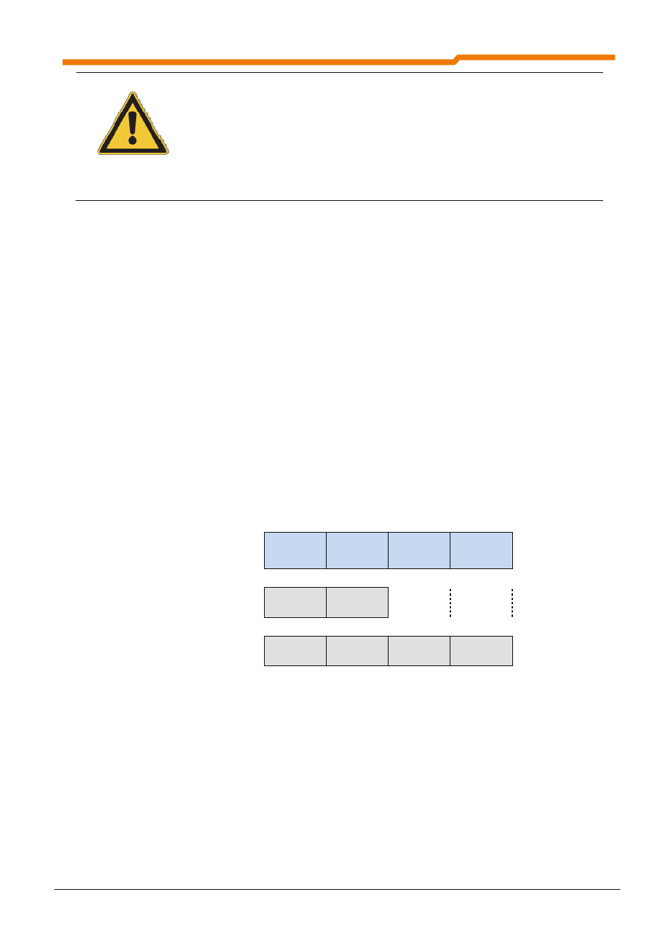
1. Word
(Byte 0,1)
2. Word
(Byte 2,3)
3. Word
(Byte 4,5)
4. Word
(Byte 6,7)
PZD area with
1x16 bit setpoint
STW
ZSW
SW1
IW1
PZD area with up to 3
16 bit setpoints
STW
ZSW
SW1
IW1
SW2
IW2
SW3
IW3
Note: 32 bit setpoints (e.g.: positions) are comprised of High or Low words (each 16 bit), whereby
according to the Little Endian format, processing starts with the Low word.