NORD Drivesystems BU0260 User Manual
Page 85
7 CANopen Data transfer
BU 0260 GB
Subject to technical amendments
85
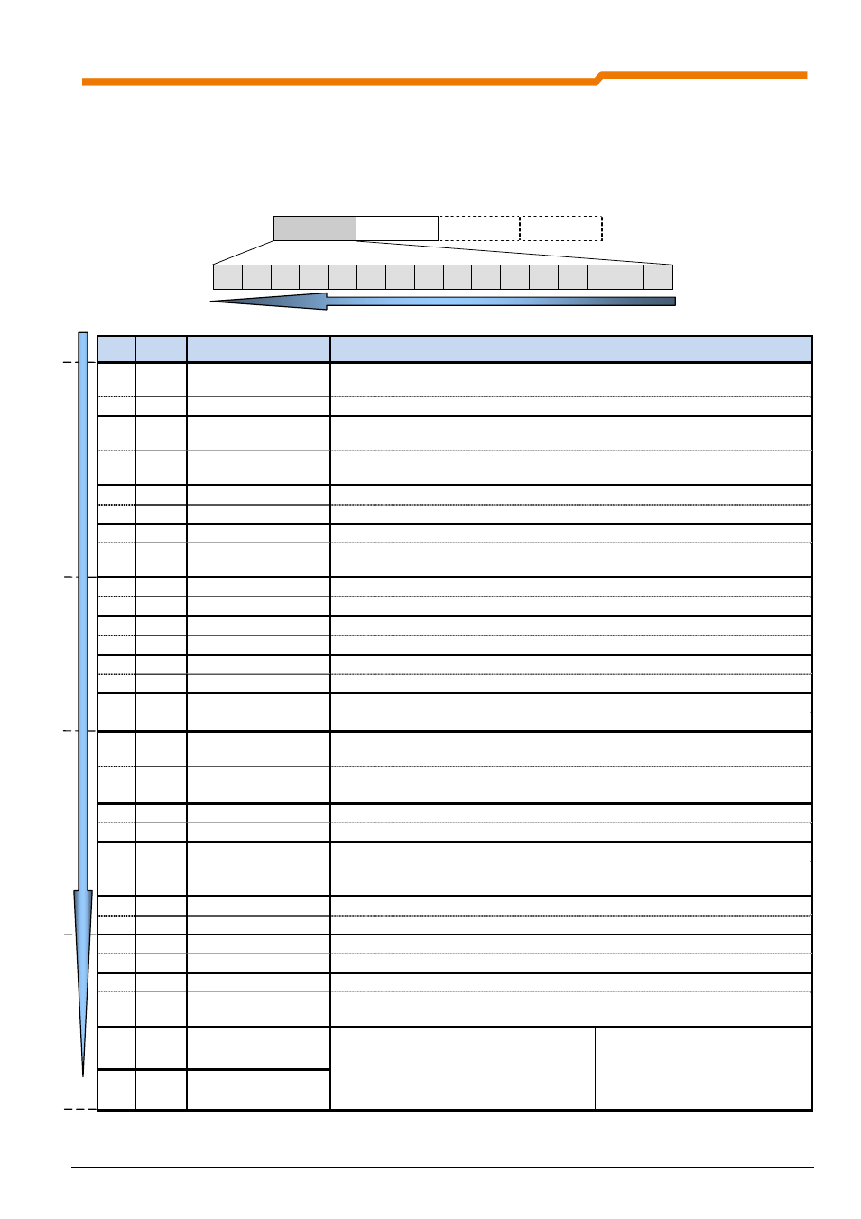
7.2.1.2 Status word (ZSW)
In the inverter response telegram, in the area of the process data the status word (ZSW) is transferred as the first
word (taking into account the "Little Endian" format. For example, a status word "ready for switch-on" corresponds
to 0B31
(hex)
, whereby in Byte 0 the value 31
(hex)
and in Byte 1 the value 0B
(hex)
are transferred.
PZD1 PZD2 PZD3 PZD4
ZSW IW1 IW2/3
IW2/3
15 14 13 12 11 10
9
8
7
6
5
4
3
2
1
0
Meaning of the individual bits:
Bit
Value Significance
Comments
0 0 Not ready for switch-
on
1
Redy for switch-on
Initialisation complete, load relay on, output voltage disabled
1 0 Not
operational
Causes: No On command, an error has occurred, OFF 2 or OFF 3 active, switch-
on disable status active.
1 Standby
ON command active, no errors. The inverter can be started with the ENABLE
OPERATION command.
2 0 Operation
disabled
1
Operation enabled
Output voltage enabled, run-up to present setpoint.
3 0 No
errors
1 Fault
Drive malfunctioning therefore out of order, if acknowledgement is successful, will
go to switch-on disabled status.
4
0
OFF 2
OFF 2 disable voltage command active
1
No OFF 2
5
0
OFF 3
OFF 3 rapid stop command active
1
No OFF 3
6
0
No switch-on disable
1
Switch-on disabled
Goes to standby status through OUT 1 command
7 0 No
warning
1
Warning
Drive still in operation, no acknowledgement necessary
8
0
Actual value not O.K.
Actual value does not match the setpoint (with posicon: Setpoint position not
reached)
1
Actual value O.K.
Actual value matches the setpoint (setpoint reached)
(with posicon: Setpoint position reached)
9
0
Local guidance
Local guidance active on device
1
Guidance required
The master is called upon to take over the guidance.
10 0
1
Bit 10 active
Bus bit 10 from the status word is set. For further details of function, please refer
to parameter P481.
11 0
1
Rotation right
Inverter output voltage has right-hand rotating field
12 0
1 Rotation
left
Inverter output voltage has left-hand rotating field
13 0
1
Bit 13 active
Bus bit 13 from the status word is set.
For further details of function, please refer
to parameter P481.
14 0/1 Actual active
parameter set Bit 0
00 = Parameter set 1
01 = Parameter set 2
10 = Parameter set 3
11 = Parameter set 4
15 0/1 Actual active
parameter set Bit 1