Brake calculations, J × n t, J × n – NORD Drivesystems B1000 User Manual
Page 744
www.nord.com
G742
G1000 – Subject to Change Without Notice
BRAKES
Brake Size Calculation
Torque and inertias below are based on the motor
speed. Load side torques must always be divided by
the gear reduction ratio. Inertias must be divided by
the
square of the gear ratio. You must also consider
any external reduction ratio outside the gearbox.
Selection for holding loads
(static)
T
req
= T
stat
= T
load
× K
Selection for stopping loads
(static + dynamic)
Ȉ
J
= J
motor
+
J
load
Typically other inertias, like the gearbox, can be ignored.
T
dyn
=
Ȉ
J × n
T
req
= (T
dyn
+
T
load
)
× K
For driving loads use: –T
load
For overhauling loads use: +T
load
Brake Work Verifi cation
W =
Ȉ
J × n
2
×
T
B
W
<
W
max
For driving loads use: +T
load
For overhauling loads use: –T
load
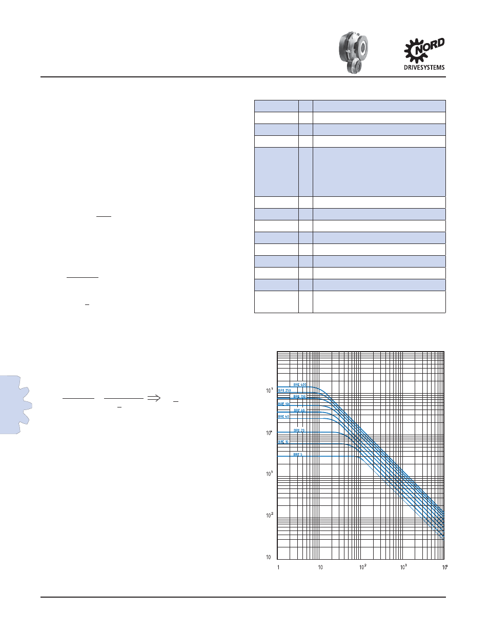
The permissible values for W
max
(Friction work)
depend on the stopping frequency. See diagram at
right.
In applications where the brake is operated fre-
quently, two brake work values should be evaluated
to ensure adequate brake life: the braking work
compared to the braking frequency and the maximum
work limit for a single operation, such as an E-stop.
Reviewing these two values will help determine the
optimal solution and ensure long brake life.
Abbreviation Key
i
2
25.7
×
t
r
5880
T
B
+
T
load
c/h
=
Number of brakes per hour
J [lb-ft
2
]
=
Inertia
J
motor
[lb-ft
2
] =
Motor inertia
i
=
System reduction ratio
K
=
Safety factors. Based on ap-
plication and according to
industry rules and practices
Hoisting >2
Hoisting with people >2..3
Travel drives 0.5 to 1.5
T
B
[lb-in]
=
Brake torque
T
dyn
[lb-in]
=
Dynamic torque
T
req
[lb-in]
=
Required brake torque
T
load
[lb-in]
=
Load torque
T
stat
[lb-in]
=
Static torque
n [rpm]
=
Motor speed
t
r
[sec]
=
Stopping time
W [J]
=
Brake work
W
max
[J]
=
Maximum brake work for one
brake operations
Braking Frequency (Brakes/hr)
Braking W
ork (J)
Brake
Calculations