Engineering nord service factor – NORD Drivesystems B1000 User Manual
Page 64
www.nord.com
INTRODUCTION
A62
G1000 – Subject to Change Without Notice
Mass Acceleration Service Factor
The mass acceleration factor (m
af
) uses a ratio of the load
inertia to motor inertia. This method of service factor
calculation can be used for both gearmotors and speed
reducers and is valid for helical and helical-bevel gear
units. For helical-worm units additional factors will need
to be taken into account including an ambient tempera-
ture factor and duty cycle factor.
Short-term and infrequent torque impulses signifi cantly
infl uence the load and selection of a gear unit. The gear
unit service factor, f
B
, takes this and other affects on the
gear unit into account.
The mass acceleration factor, m
af
, represents the relation-
ship between external low-speed output side and high-
speed input side masses. The mass acceleration factor
signifi cantly infl uences the level of torque impulses in
the gear unit upon start-up and braking procedures, and
upon vibration. The external mass moments of inertia
also include the load, such as the material transported
on conveyor belts. We ask you to consult with NORD if
the m
af
> 10, if there is a large play in transfer elements,
vibration in the system, uncertainty regarding the load
classification, or you are in doubt.
For applications with relatively high external mass
moments of inertia, m
af
> 2 (i.e. travel drives, slewing
gears, rotary tables, gear drives, agitators, and surface
aerators), we recommend braking torque that does not
exceed 1.2 times the rated motor torque. If a higher
breaking torque is to be used, this must be considered
when selecting the gear unit.
1. Calculate mass acceleration factor:
m
af
=
J
load
x
1
2
J
load
= External load inertia including all components
of the system outside of the reducer
J
motor
= Motor inertia. For NORD motors see pages 712 - 718
If m
af
≤ 0.25 use curve A (uniform operation)
Light conveyor screws, fans, assembly lines, light convey-
or belts, small agitators, elevators, cleaning machines,
fi lling machines, inspection machines, belt conveyors.
If ≤ 0.25 m
af
≤ 3.00 use curve B (moderate shocks)
Coilers, feed-mechanism drivers for woodworking ma-
chines, dumbwaiters, balancing machines, thread cut-
ting machines, medium-sized agitators and mixers,
heavy conveyor belts, winches, sliding doors, manure
scrapers, packing machines, concrete mixers, overhead
crane traveling mechanisms, mills, bending machines,
gear pumps.
If 3.01 ≤ m
af
10.00 use curve C (heavy shocks)
Heavy mixers, shears, presses, centrifuges, rolling stands,
heavy winches and lifts, grinding mills, stone crushers,
bucket elevators, punching machines, hammer mills, ec-
centric presses, folding machines, roller tables, tumbling
barrels, vibrators, shredders.
2. Determine the cycles/hour. A cycle is a start or hard
stop, where a hard stop decelerates the motion of
the system when a mechanical brake is activated.
3. Determine the run time in hours/day.
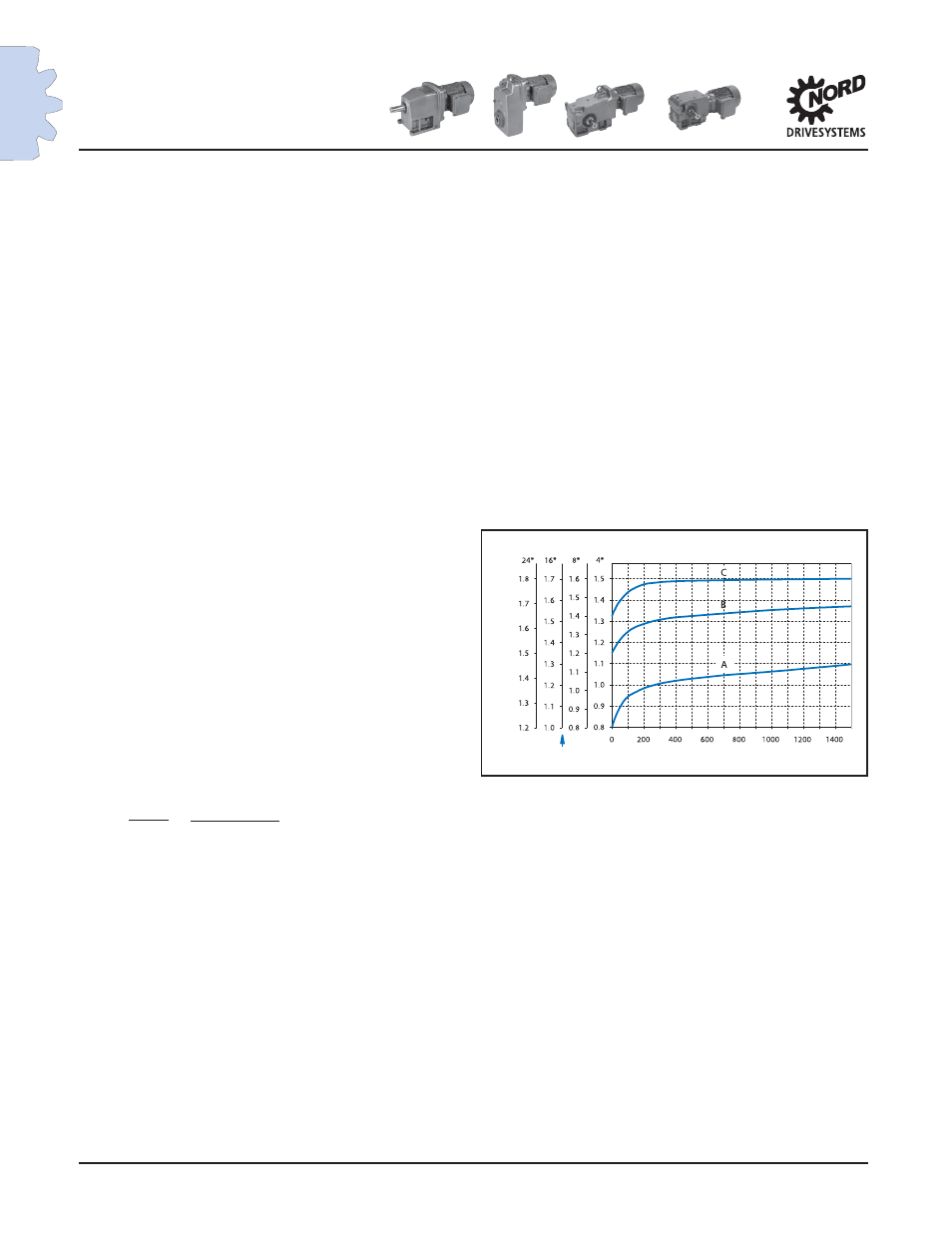
4. Using the chart; locate the cycles/hour on the
horizontal axis and move vertically up to intersect
curve A, B, or C based on the m
af
. From the
intersection point, move horizontally left to the
service factor f
B
based on the run time in hours/day.
EXAMPLE for Inline, Shaft mount, or Bevel gearmotor:
A smooth running conveyor operates 24 hours/day with
500 cycles/hour. The calculated m
af
= 0.16, therefore use
curve A for this type of application.
From the chart, fi nd 500 cycles/hour and follow the axis
vertically up until you intersect curve A. From the inter-
section point, move horizontally left to fi nd the service
factor f
B
= 1.4 based on 24 hours/day operation. Consult
the selection pages of the catalog to fi nd a gearmotor
with a service factor f
B
= 1.4 or greater.
f
B
* Run time hours/day
Cycles / Hour
S
er
vic
e F
ac
tor
Engineering
NORD
Service Factor
J
motor
reducer ratio
(
(