Mounting positions, Mounting confi guration – NORD Drivesystems B1000 User Manual
Page 20
www.nord.com
A18
INTRODUCTION
G1000 – Subject to Change Without Notice
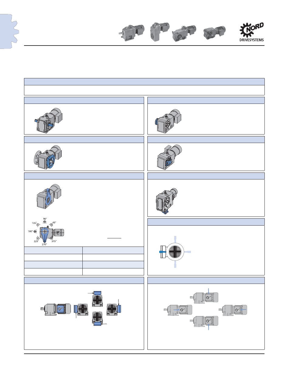
Mounting
Positions
Mounting Confi guration
NORD provides gearmotors, speed reducers and motors that can be confi gured very fl exibly to suit customer
needs. When ordering it is benefi cial that the drive be specifi ed exactly the way you want it delivered.
Mounting Positions
Basic mounting
M1 M2 M3 M4 M5 M6
Right-angle with solid shaft
Right-angle with shrink disc
Shaft Side A
Shrink Disc Side A
Shaft Side B
Shrink Disc Side B
Shaft Side A+B
Right-angle fl ange mount units
Right-angle with hollow shaft cover
Flange Side A
Hollow Shaft Cover Side A
Flange Side B
Hollow Shaft Cover Side B
Flange Side A+B
Right-angle with torque arm
Bottom mount torque arm
Torque Arm Side A
Torque Arm Side A
Torque Arm Side B
Torque Arm Side B
Shaft mount torque arm orientation
Brake motor with hand release lever
Orientation
Hand Release Lever Pos. 1
Hand Release Lever Pos. 2
92 - Bevel
90˚ - 315˚, Every 45º
Hand Release Lever Pos. 3
90 - Bevel
45˚ - 270˚, Every 45º
Hand Release Lever Pos. 4
Helical-worm
45˚ - 270˚, Every 45º
Helical-worm 02040
90˚, 180˚, 270˚, Every 90º
Terminal box location
Conduit entry location
Terminal Box Position 1
Terminal Box Position 3
Conduit Entry Location I Conduit Entry Location III
Terminal Box Position 2
Terminal Box Position 4
Conduit Entry Location II Conduit Entry Location IV
A Side
B Side
A Side
B Side
A Side
B Side
A Side
B Side
A Side
B Side
Hand Release
Lever Position 2
Hand Release
Lever Position 1
Hand Release
Lever Position 4
Hand Release
Lever Position 3
A Side
B Side
Conduit Entry - I
Conduit Entry - IV
Conduit Entry - III
Conduit Entry - II
Terminal Box
Position 1
Terminal Box
Position 2
Terminal Box
Position 3
Terminal Box
Position 4
Denotes Brakemotor