In-line overhung load calculation tables – NORD Drivesystems B1000 User Manual
Page 55
www.nord.com
A53
G1000 – Subject to Change Without Notice
INTRODUCTION
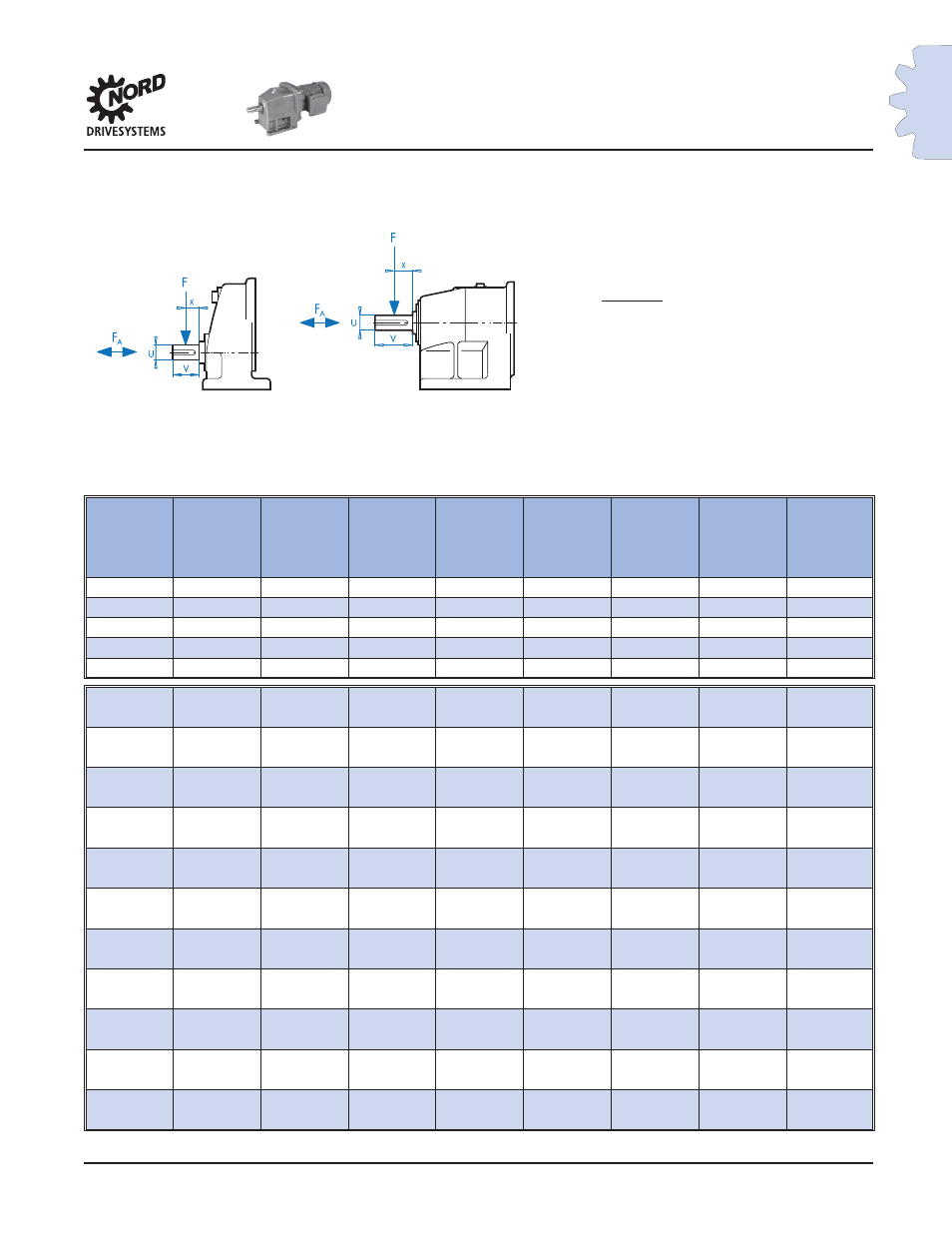
In-line Overhung Load
Calculation Tables
Calculation Table for OHL at Output Shaft for In-line Units
Gearbox
Type
y
z
c
c
f
U
V
T
2max
Standard
Bearings
VL
Bearings
[in]
[in]
[lb-in]
[lb-in]
[in]
[in]
[in]
[lb-in]
SK 11E
2.56
3.35
*
*
1.54
0.750
1.50
513
SK 21E
3.03
4.02
*
*
1.97
1.000
2.13
681
SK 31E
4.11
5.30
*
*
2.74
1.250
2.75
1637
SK 41E
4.39
5.77
*
*
2.64
1.375
3.00
2567
SK 51E
4.92
6.50
*
*
2.91
1.625
3.25
4354
SK 02
2.51
3.30
531
885
0.46
0.750
1.50
876
SK 03
973
SK 12
2.89
3.88
1,062
1,593
0.55
1.000
2.13
1628
SK 13
1717
SK 22
3.39
4.57
1,682
2,655
0.55
1.250
2.75
3310
SK 23
3009
SK 32
4.43
6.00
3,452
5,310
1.18
1.625
3.25
6284
SK 33
5947
SK 42
4.84
6.61
3,717
6,461
1.18
1.875
3.50
11,009
SK 43
11,408
SK 52
5.89
8.05
8,142
13,806
1.38
2.250
4.00
17,912
SK 53
19,753
SK 62
7.52
10.08
12,921
21,771
1.38
2.500
5.00
27,612
SK 63
32,745
SK 72
8.35
11.10
18,851
39,383
1.46
3.000
5.50
41,666
SK 73
50,003
SK 82
9.78
13.13
37,254
60,977
1.50
3.500
6.75
64,127
SK 83
81,243
SK 92
10.94
15.08
71,420
110,625
1.61
4.250
8.50
95,359
SK 93
123,900
SK 102
12.74
17.64
131,511
202,134
1.81
5.250
10.00
153,698
SK 103
204,966
* - Consult Factory for calculation
R
R
F
OHL
= Calculated OHL on gearbox shaft [lb]
T = Load torque on shaft [lb-in]
d
0
= Pitch diameter of overhung component [in]
f
z
= Power transmission component factor
F
OHL
=
2 x T x f
z
After calculating
F
OHL
compare to the
overhung load capacity found in the tables.
F
OHL
≤ F
R
or F
R1
If
F
OHL
exceeds the rated capacity (F
R
or F
R1
) of the
speed reducer then either heavy-duty bearings
or a larger gearbox must be selected.
d
o