Selection information – NORD Drivesystems B1000 User Manual
Page 14
www.nord.com
INTRODUCTION
A12
G1000 – Subject to Change Without Notice
Selection
Information
NORD Mass Acceleration Service Factoring
NORD often uses a calculation based system to prop-
erly assign a service factor. This system considers hours
of operation per day, the severity of the application
and the number of times the equipment is cycled. See
page 72 for additional detail.
4. Gearbox Type & Input
NORD gear drives are available in a number of
mechanical confi gurations including:
• Helical
in-line
• Clincher™ shaft mount
• Right-angle
helical-bevel
• Right-angle
helical-worm
NORD’s modular design allows for a number of differ-
ent inputs to be added to NORD reducers including:
• Integral
motor
• NEMA-C and IEC motor adapter
• Solid input shaft
• Servo motor adapter
• Sugar scoop mount
• Top motor mount platform
• NORDISC
TM
variable speed friction drives
• Titan
TM
variable speed belt boxes
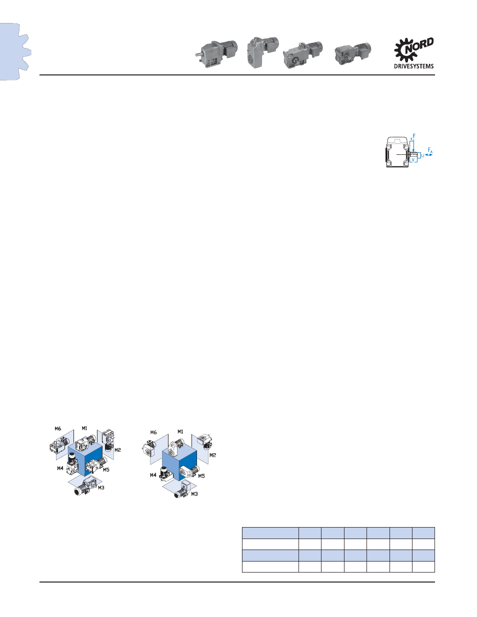
5. Mounting Position
The gearbox mounting position is an important and
often overlooked specifi cation. The mounting posi-
tion determines how much oil the gear reducer re-
quires, in addition to determining the position of the
oil drain, oil fi ll and vent on the gear drive. NORD
offers six basic mounting positions. If your applica-
tion requires a variation from the six basic mounting
positions, please contact NORD.
Many gearbox and motor options require a location
designation. For example a right-angle helical-bev-
el unit with a single solid shaft extension requires a
shaft extension side location. Please see page 23 for
additional options that require location designation.
6. Options
NORD offers a number of mechanical, protective,
paint & lubrication options for gear reducers & mo-
tors. Please see page 25 for gear unit options & refer
to the motor section (Section G) for motor options.
7. Checks
Overhung Load
An overhung or radial load exists when a force is
applied at right-angles to a shaft beyond the shaft’s
outermost bearing. Pulleys, sheaves and sprockets
will cause an overhung load when used as a power
take-off. The amount of overhung load will vary,
depending on the type of power take-off used and
where it is located on the shaft.
Overhung load [FQ] can be found in the gearmotor
rating tables and input shaft overhung load ratings
[FQ1] can be found on pages 58 - 69. Overhung load
capacities should not exceed the values in the table
to ensure long bearing life. Overhung load capacities
are to be applied at the midpoint of the shaft exten-
sion and without thrust loads.
To calculate overhung load see page 58.
Thrust Loads (Axial)
Loads that are directed towards or away from the
gearbox along the axis of the shaft are called thrust
or axial loads. Output shaft thrust capacity [FA] can
be found in the gearmotor rating tables. Input shaft
capacity [FA1] can be found on pages 68. Thrust load
capacities should not exceed the values listed in the
tables to ensure long bearing life. Thrust load capaci-
ties are listed for pure axial loads with no overhung
load. Contact NORD for combination loads or a more
exact examination of the application.
NEMA C-face Motor Weight Limits
When mounting a motor to a NORD NEMA C-face
motor adapter it is important to consider the motor’s
weight. Following is a table that includes the maxi-
mum motor weight the NEMA adapter can support.
If the motor exceeds the listed weight it must be ex-
ternally supported. When a C-face mounted motor
is externally supported care must be taken to ensure
that the support system does not impose additional
pre-loads on the NEMA motor adapter.
NEMA Weights
Motor FRAME
56C
143TC 145TC 182TC 184TC 210TC
Max Weight [lb]
66
88
110
130
175
220
Motor FRAME
250TC 280TC 324TC 326TC 365TC
Max Weight [lb]
440
550
770
1100
1540
M1
M2
M6
M4
M3
M5
R