Inverter sk 300e trio – NORD Drivesystems B1000 User Manual
Page 709
www.nord.com
G707
G1000 – Subject to Change Without Notice
MOTORS
Step 4: Customer I/O Based
Control Interface Option - SK CU2-STD
The standard I/O based control available via the Trio
Interface can be expanded via selection of an optional
Customer Unit, SK CU2-STD, that plugs into the Trio
Interface. Interface I/O points are listed on the following
chart:
I/O on standard Trio Interface Additional I/O on
SK CU2-STD Option
1 X programmable digital input
4 X programmable digital input
5 VDC and 15 VDC
power supplies
2 X single-ended analog
inputs
RS 485 interface via M-12
connector and terminals
+10 VDC reference supply
1 X programmable relay out-
put
1 X selectable/programmable
analog/digital output
PID control access
Step 5: Cover Mounted
Technology Unit (TU) Options
A variety of pre-engineered plug in Technology Unit
(TU) options can be ordered to replace the standard
blank cover of the SK 300E inverter. Only a single TU
can be installed on the inverter at a given time. Avail-
able units include operator and fi eld bus interfaces:
Technology Unit (TU) Name Description
SK TU2-POT
Analog reference potentiometer box
with L/Off/R control switch
SK TU2-CTR
Digital control/programmer with 4
digit, 7 segment LED display
SK TU2-PBR
Profi bus fi eld bus interface
SK TU2-PBR-24V
Profi bus fi eld bus interface powered
by customer 24 VDC supply
SK TU2-PBR-KL
Profi bus fi eld bus interface with
clamp on connectors
SK TU2-AS1
AS (Actuator/Sensor) Interface
SK TU2-CAO
CANopen fi eld bus interface
SK TU2-DEV
DeviceNet fi eld bus interface
SK TU2-IBS
InterBus fi eld bus interface
SK TU2-DECKEL
Original blank cover for TU slot
(in case TU option is removed)
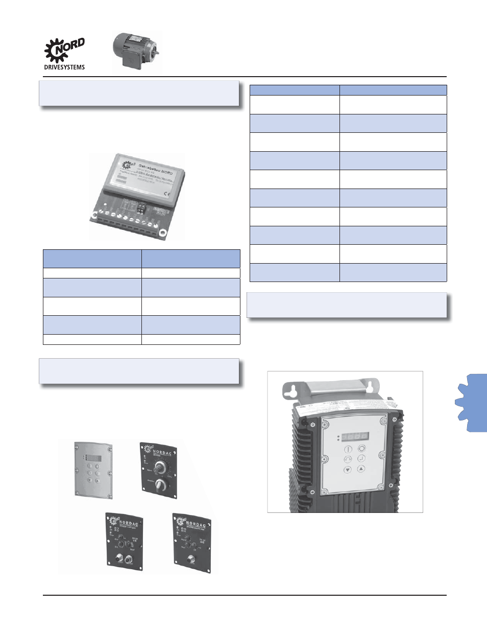
Step 6: Wall Mounting Option Kit,
SK WMK-DA1
The wall mounting kit enables mounting the SK 300E
inverter on a nearby wall or the machine instead of
directly on the NORD motor or gearmotor. The Trio
Interface (TI) is still required and all other options can
be used.
Inverter
SK 300E Trio