Inverter sk 300e trio – NORD Drivesystems B1000 User Manual
Page 710
www.nord.com
G708
G1000 – Subject to Change Without Notice
MOTORS
Step 7 : Additional Tools &
Related Interface Options
In addition to the cover mounted SK TU2-CTR option,
there are several additional options that enable sim-
ple programming and control of the SK 300E:
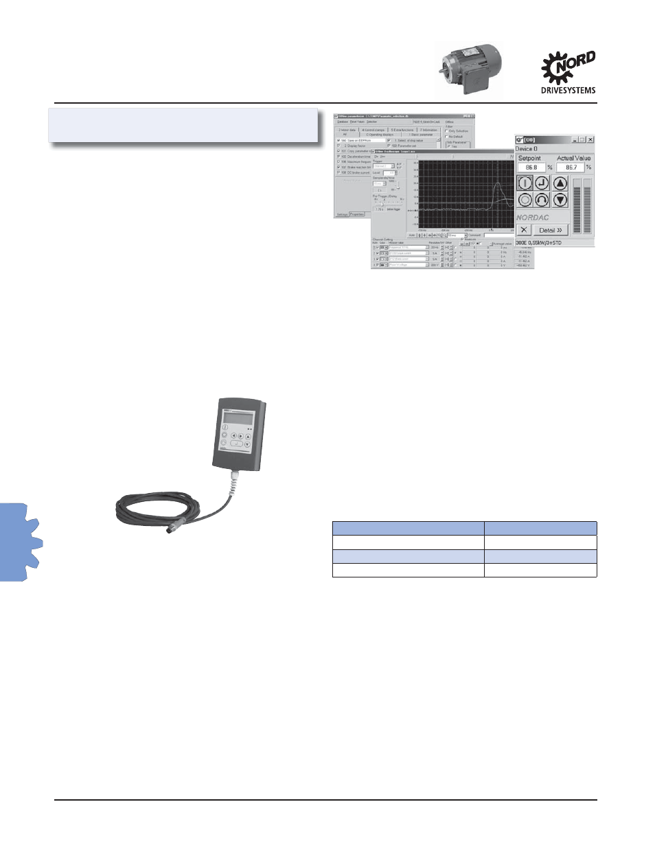
Handheld Parameter Box (P-Box)
with 10 foot cable, SK PAR-2H
Detachable external add-on unit that can be used to
program and display parameters and control the op-
eration of the connected SK 300E. Features multi-line
plain text display selectable in six languages. Manages
and stores up to fi ve unique inverter programs. Cable
plugs into M-12 connector in side of Trio Interface.
Panel Mount Parameter Box (P-Box), SK PAR-2E
Panel Mount version of Parameter Box with same
functionality as SK PAR-2H. Installs in cut-out in front
of customer supplied operator panel. Interface con-
nection is performed by customer with their shielded
cable via terminals on SK PAR-2E and SK 300E.
NORD CON Software –
Available free at NORD Website
NORD CON Software is a Windows-based PC program
that enables the control and programming of NOR-
DAC Frequency Inverters. It provides for accessing
up to 31 Frequency Inverters simultaneously via the
RS485 interface. It features both off-line and on-line
programming and data management modes.
NORD CON allows user to:
• Program inverters & upload/download parameter fi les
• Control connected inverters for test/troubleshooting
• Monitor connected inverters and examine up to four
variables versus time with built-in oscilloscope feature
• Display parameter information in six languages
Optional accessories required to interface user PC to
SK 300E via NORD CON are:
SK IC1 – RS 485 to RS 232 interface converter
Enables communication between RS 232 port on com-
puter and RS 485 port on SK 300E
Cable SK 300E –
10 foot cable that connects between the 9-Pin D shell
connector on the SK IC1 and the M-12 connector on
the side of the SK 300E Trio Interface.
Electromechanical Brake Interface
& Coil Voltage Selection
As standard, the SK 300E provides a dedicated high
voltage DC power supply and coordination software
to directly control an Electromechanical Brake. This is
equivalent to using a half wave rectifi er, so the brake
coil voltage must be specifi ed per the following chart:
Nominal Inverter AC Input Voltage Brake Coil Voltage
440 – 480 VAC
205 VDC
200 – 240 VAC
105 VDC
380 – 415 VAC
180 VDC
The brake gets connected to terminals +Br and –Br on
the Trio Interface
Motor overload protection
Electronic motor overload protection is provided as
standard on the SK 300E inverter. If required, more
precise protection can be achieved via the use of mo-
tor thermostats (TW) or thermistor sensors (TF). See
page 698 for detailson these motor options. These
devices can be interfaced to the SK 300E via the pro-
grammable digital input to indicate a motor over
temperature error.
Inverter
SK 300E Trio