2 instrument description, Instrument description, Partlow v7 – West Control Solutions DataVU 7 User Manual
Page 15
15
2 Instrument Description
H
The connection diagram is described in the Installation
Instructions 59488/59490. When the paperless recorder is
delivered, a printed version of the installation instructions is
included.
59488
Installation instructions for recorder
with zinc die-cast panel
59490
Installation instructions for recorder
with stainless steel panel
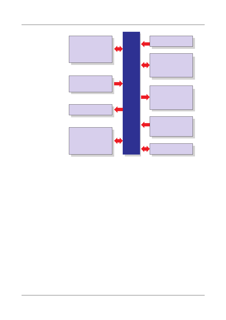
Setup program
PC Eval. software (PCA3000)
PCA Communications software
Software
Internal channels
18x math channels
18x logic channels
27x counters / integrators
Inputs/outputs
0…18 analog inputs max.
0…24 binary inputs/outputs max.
(maximum of 3 module slots,
can be fitted with 6 analog inputs
or 3 analog inputs
and 8 binary inputs/outputs)
Display/operation
Power supply
Display
Operation
5.5" TFT color display,
320 x 240 pixels,
256 colors
control knob or touchpad
(left, right, press)
additionally
up to 24 analog inputs and
up to 24 binary inputs
Inputs via interface
1 relay (standard)
additionally
6 relays (option)
Relay outputs
AC 100...240V +10/-15%,
48...63Hz
AC/DC 20...30V, 48...63Hz
Interface
as standard
1x RS232/RS485
option
1x PROFIBUS-DP
1x Ethernet 10/100 Mbits/sec
4x USB interfaces
1x RS232 (barcode reader)
internal memory
256 Mbytes
external memory
CompactFlash card and
USB memory stick
Meas. data memory
Partlow V7