Option slot 3 - transmitter power supply module, Option slot a connections, Option slot a connections - digital input module – West Control Solutions ProVU 4 User Manual
Page 36
ProVU4 Controller, Profiler & Recorder/Controller - Product Manual
59407, Issue 1 – March 2008
Wiring Instructions
Page 35
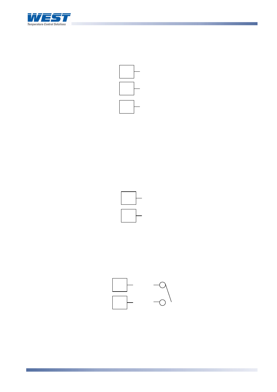
Option Slot 3 - Transmitter Power Supply Module
If option slot 3 is fitted with a transmitter power supply module, make connections as
illustrated. The output is an unregulated 24V DC, 22mA supply.
Figure 31.
Option Slot 3 - Transmitter Power Supply Module
Option Slot A Connections
Option Slot A Connections – Basic Auxiliary Input Module
If option slot A is fitted with a basic auxiliary input module, connect as shown. It is
recommend that the full auxiliary input (Option Slot B) is used instead, as this has additional
features and leaves option slot A free for other modules.
Figure 32.
Option Slot A – Basic Auxiliary Input Module
Option Slot A Connections - Digital Input Module
If a digital input module is fitted in option slot A, this may be connected to either voltage free
contacts (e.g. switch or relay), or a TTL compatible voltage. Connections are shown below.
Figure 33.
Option Slot A – Digital Input Module
Option Slot A Connections - Ethernet Communications Module
If option slot A is fitted with the Ethernet communication module, a standard RJ45 connector
is accessible from the top of case. No rear connections are required.
10
11
_
12
+
16
17
_
+
16
17
_
+