Local setpoints, Lock codes, Logical combination of alarms – West Control Solutions ProVU 4 User Manual
Page 144: Logical alarm combinations
ProVU4 Controller, Profiler & Recorder/Controller - Product Manual
59407, Issue 1 – March 2008
Glossary
Page 143
Local Setpoints
Local setpoints are target values that are stored inside the controller. These are normally
entered by from the front keypad, but can also be set via a serial communications link.
The instrument can have up to two setpoints. Local Setpoint 1 and/or an Alternative Setpoint.
The Alternative Setpoint can be chosen from Local Setpoint 2 or a remote setpoint from an
auxiliary input. One setpoint can be chosen as the active at using the Setpoint Selection.
The value of the setpoints can be adjusted between the Setpoint Upper Limit and Setpoint
Lower Limits.
Also refer to: Alternative Setpoint, Auxiliary Input, Remote Setpoint, Serial Communications,
Setpoint, Setpoint Lower Limit, Setpoint Upper Limit, and Setpoint Select.
Lock Codes
The four-digit codes required when entering the Setup Wizard, Configuration Mode, Tuning
Menu, Supervisor Mode, USB Menu, Recorder Menu and Profiler Setup Menu. These menus
can be selected from the Main Menu. The correct code must be entered to gain access. If
unlimited access is required for any of the menus, its lock can be turned off by setting the
value to OFF. Refer to the Lock Code View information in the Configuration & Use section.
Settings = 1 to 9999 or OFF.
Default value = 05:00
Also refer to: Configuration Mode, Main Menu, Profiler Setup Menu, Recorder Menu, Setup
Wizard, Supervisor Mode, Tuning Menu and USB Menu.
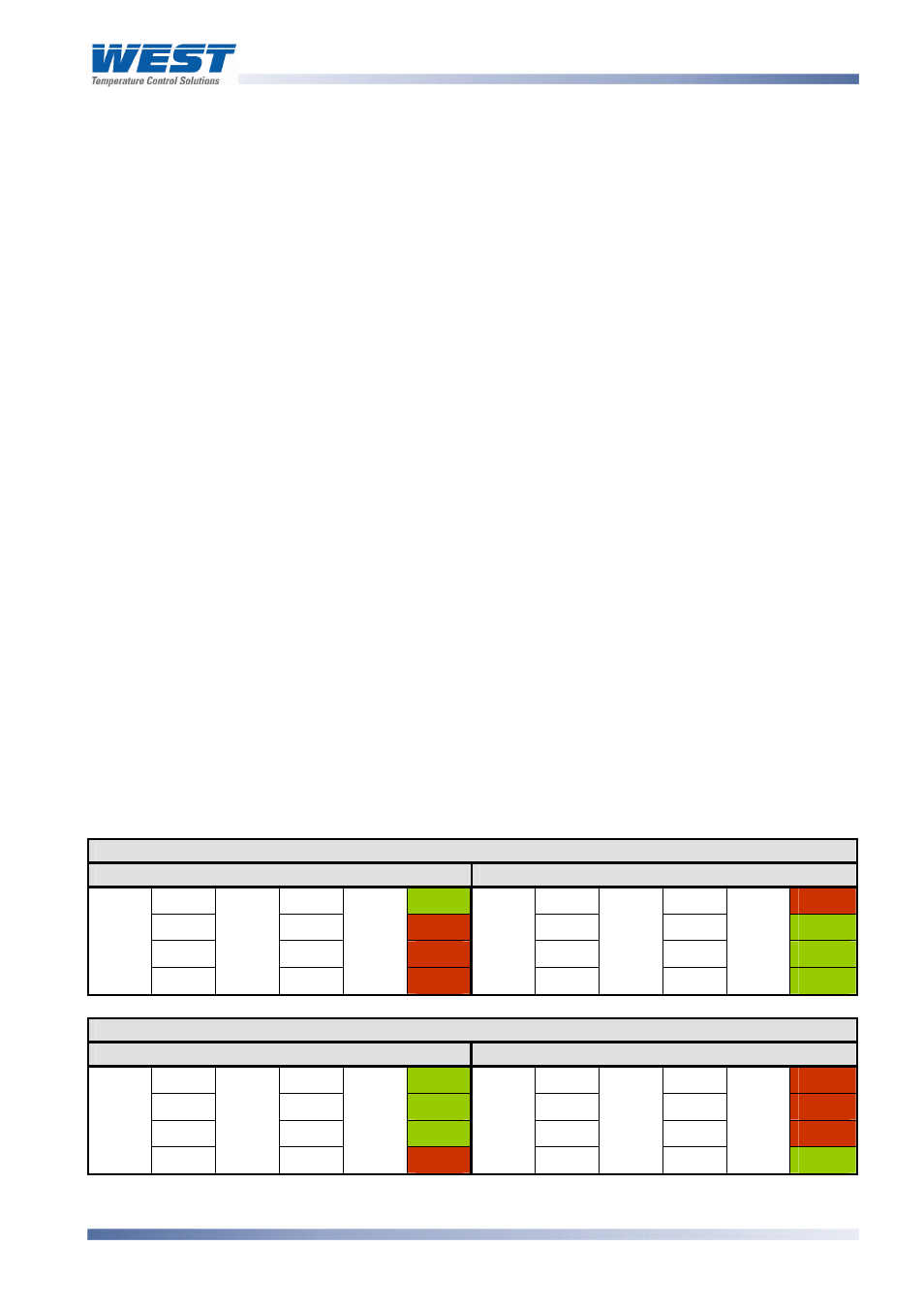
Logical Combination of Alarms
Outputs for alarms may be combined to create a Logical OR situation. Possible combinations
are: Alarms 1 to 2; 1 to 3; 1 to 4 or 1 to 5.
Outputs for alarms & events may be combined to create a Logical AND situation. Possible
combinations are: Alarm 1 & Event 1; Alarm 2 & Event 2; Alarm 3 & Event 3; Alarm 4 & Event
4; and Alarm 5 & Event 5.
Any suitable output may be assigned as a logical output and can be configured for reverse
action or direct action.
Also refer to: Alarm Operation, Alarm Types, Output Configuration and Profile Events.
Table 28. Examples Of Logical Alarm Outputs
Logical OR: Alarm 1 OR Alarm 2
Direct Acting
Reverse-Acting
OFF
OFF
OFF
OFF
OFF
ON
ON
OFF
ON
ON
OFF
OFF
OFF
ON
ON
OFF
ON
OFF
ALARM 1
ON
ALARM 2
ON
OUTPUT
ON
ALARM 1
ON
ALARM 2
ON
OUTPUT
OFF
Logical AND: Alarm 1 AND Alarm 2
Direct Acting
Reverse-Acting
OFF
OFF
OFF
OFF
OFF
ON
ON
OFF
OFF
ON
OFF
ON
OFF
ON
OFF
OFF
ON
ON
ALARM
1
ON
ALARM 2
ON
OUTPUT
ON
ALARM 1
ON
ALARM 2
ON
OUTPUT
OFF