Bar graphs, Bias (manual reset), Bumpless transfer – West Control Solutions ProVU 4 User Manual
Page 137: Cascade control
ProVU4 Controller, Profiler & Recorder/Controller - Product Manual
Page 136
Glossary
59407, Issue 1 – March 2008
Bar Graphs
The instrument displays a bar-graph in the base operation mode screen. This bar-graph will
be uni-directional or bi-directional depending on the information to be displayed. This can be:
PID Power Output (single control = uni-directional, dual control = bi-directional), Control
Deviation (bi-directional) or for Data Recorder version %Memory Used (uni-directional).
Also refer to: Control Deviation, Data Recorder, Display Configuration, Operation Mode, Main
Menu and PID
Bias (Manual Reset)
Used to manually bias proportional output(s) to compensate for the control deviation errors
due to process load variations. Bias is expressed as a percentage of output power. This
parameter is not applicable if the Primary output is set to ON-OFF control. If the process
variable settles below setpoint use a higher Bias value to remove the error, if the process
variable settles above the setpoint use a lower Bias value. Lower Bias values will also help to
reduce overshoot at process start up. Integral action performs a similar function automatically
when using PI or PID control.
Settings = 0 to 100% (-100% to +100% for dual control).
Default value = 25%.
Also refer to: Control Deviation, Integral Action, ON/OFF Control, PI Control, PID,
Proportional Control, Process Variable, and Setpoint.
Bumpless Transfer
A method used to prevent sudden changes to the correcting variable, when switching
between automatic PI or PID and Manual control modes. During a transition from PI or PID to
Manual control, the initial Manual Power value is set to equal the previous automatic mode
value. The operator then adjusts the value as required. During a transition from Manual
control to PI or PID, the initial automatic value is set to equal the previous Manual mode
value. The correcting variable level will gradually adjusted by the control algorithm at a rate
dependant on the integral action resulting from the Integral Time Constant. Since integral
action is essential to Bumpless Transfer, this feature is not available if Integral is turned off.
Also refer to: Correcting Variable, Integral Action, Manual Mode, PI and PID.
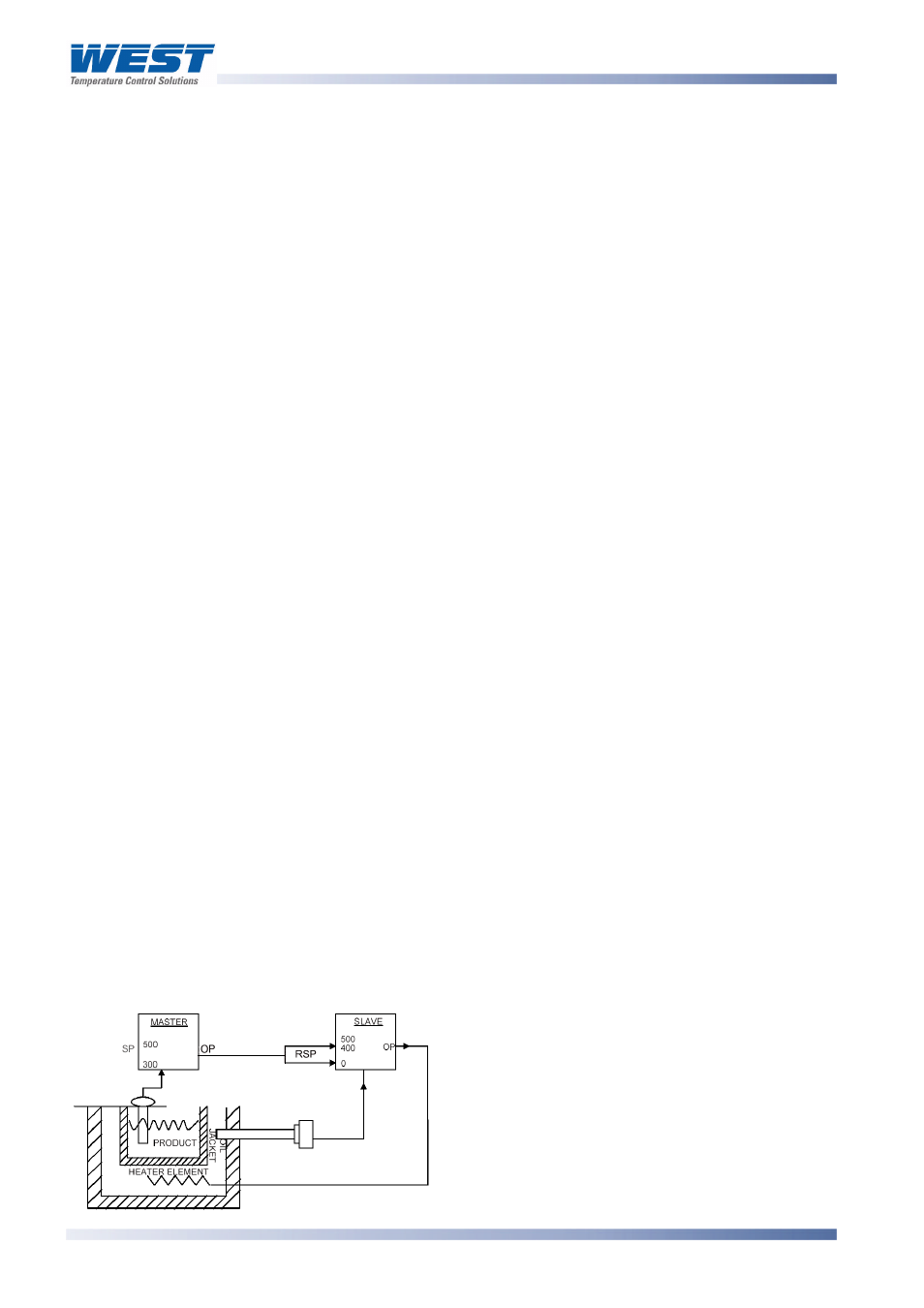
Cascade Control
Applications with two or more capacities (such as heated jackets) are inherently difficult for a
single instrument to control, due to large overshoots and unacceptable lags. The solution is
to cascade two or more controllers, each with its own input, in series to form a single
regulating device. The product setpoint temperature is set on the master controller. This is
compared to the product temperature, and the master’s PID output (mA or VDC) is fed into
the auxiliary input of the slave controller as a remote setpoint input. The RSP is scaled to suit
any expected temperature. The slave loop’s natural response time should ideally be at least
5 times faster than the master.
In the example, the maximum input
represents 400ºC, thus restricting the
jacket temperature. At start-up the master
compares the product temperature
(ambient) to its setpoint (300ºC) and gives
maximum output. This sets the maximum
(400ºC) setpoint on the slave, which is
compared to the jacket temperature
(ambient) giving maximum heater output.