2 zones, 3 power, Zones 4.23.3: power – Fire-Lite MS-9200UDLSC Addressable Fire Alarm Control Panel User Manual
Page 146
146
MS-9200UDLS Series Manual — P/N 52750:H 4/14/2014
Operating Instructions
Read Status
•
Pre-Signal Yes/No (for detectors and monitor modules)
•
Zone Assignments (five maximum)
•
Chamber Value
•
Adjective/Noun descriptor
•
Silenceable Yes/No (for control modules)
•
MNS Override Enabled/Disabled (for control modules)
4.23.2 Zones
Pressing 2 while viewing Read Status Screen #1 will cause the following screens to be displayed:
From the preceding screens, the control panel operator can view:
•
Zones Installed - all software zones programmed into the system (99 maximum)
•
Zones Enabled - all software zones that are enabled
•
Zones Disabled - all software zones that have been disabled
•
Special Purpose - on or off programming for Special Purpose Zones 97 reserved for PAS, 98
reserved for Pre-signal and 99 reserved for Two Stage
•
Zone Type - the Type assigned to each installed zone (default is Alarm)
•
Zone Message - the Message assigned to each installed zone
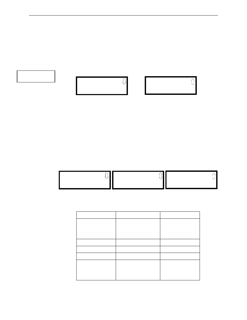
4.23.3 Power
Pressing 3 while viewing Read Status Screen #1 will cause the following screens to be displayed:
The following table lists the circuit being measured, possible conditions and their respective
voltage ranges:
READ STATUS
1=SYSTEM POINT
2=ZONES
3=POWER
Read Status Screen #1
ZONES
1=ZONES INSTALLED
2=ZONES ENABLED
3=ZONES DISABLED
Zones Screen #1
ZONES
1=SPECIAL PURPOSE
2=ZONE TYPE
3=ZONE MESSAGE
Zones Screen #2
Circuit
Condition
Voltage Range
Battery
Normal Battery (nominal)
27.05 to 28.15 VDC
Low Battery
20.0 to 20.8 VDC
No Battery
0 to 18.36 VDC
24V Resettable
Normal
21.25 to 27.50 VDC
24V Nonresettable
Normal
21.25 to 27.50 VDC
Charger
Normal
21.87 to 29.84 VDC
NAC 1 - NAC 4
Normal
-1.3 to -1.6 VDC
Open Circuit
-2.3 to -2.5 VDC
Short Circuit
0 to 1.0 VDC
POWER
BATTERY 27.21V
24 V RST 25.31
Power Screen #1
POWER
CHARGER 28.36V
NAC 1 -1.49V
NAC 2 -1.49V
Power Screen #2
POWER
NAC 3 -1.49V
NAC 4 -1.49V
Power Screen #3