A4.4 pid computation details, A4.4.2 pid control parameters, A4.5 control output – Yokogawa Wireless Temperature Transmitter YTA510 User Manual
Page 80: A4.4, A4.4.2, A4.5, A4-4
A4-4
IM 01C50T02-01E
Index Parameter Name
Default
(factory setting)
Write
Valid Range
Description
61
HI_ALM
—
—
As above
62
LO_ALM
—
—
As above
Reset when the PV value has increased
above [LO_LIM + ALM_HYS].
63
LO_LO_ALM
—
—
As above
64
DV_HI_ALM
—
—
Alarm that is generated when the value of [PV
- SP] has exceeded the DV_HI_LIM value.
Other features are the same as HI_HI_ALM.
65
DV_LO_ALM
—
—
Alarm that is generated when the value of [PV
- SP] has decreased below the DV_LO_LIM
value. Other features are the same as
LO_LO_ALM.
A4.4 PID Computation Details
A4.4.1 PV-proportional and -derivative
Type PID (I-PD) Control Algorithm
For PID control, the PID block in an YTA employs
the PV-proportional and PV-derivative type PID
control algorithm(referred to as the I-PD control
algorithm) in Auto and RCas mode. The I-PD
control algorithm ensures control stability against
sudden changes in the setpoint, such as when
the user enters a new setpoint value. At the
same time, the I-PD algorithm ensures excellent
controllability by performing proportional, integral,
and derivative control actions in response to
changes of characteristics in the controlled process,
changes in load, and occurrences of disturbances.
In Cas mode, PV derivative type PID control
algorithm (referred to as the PI-D control algorithm)
is employed in order to obtain better performance
against the changes in the setpoint. The algorithm
is automacially switched by the block according
to the mode. A basic form of each algorithm is
expressesd in the equation below.
I-PD Control Algorithm (in Auto / RCas mode)
∆MVn = K {∆PVn + (PVn − SPn) + ∆(∆PVn)}
∆T
Ti
Td
∆T
PI-D Control Algorithm (in Cas mode)
∆MVn = K{∆(PVn−SPn)+ (PVn−SPn)+ ∆(∆PVn)}
∆T
Ti
Td
∆T
Where,
∆MVn = change in control output
∆PVn = change in measured (controlled) value
= PVn - PVn-1
∆T
= control period = period_of_execution in
Block Header
K
= proportional gain = GAIN (= 100/
proportional band)
Ti
= integral time = RESET
Td
= derivative time = RATE
The subscripts, n and n-1, represent the time
of sampling such that PVn and PVn-1 denote
the PV value sampled most recently and the PV
value sampled at the preceding control period,
respectively.
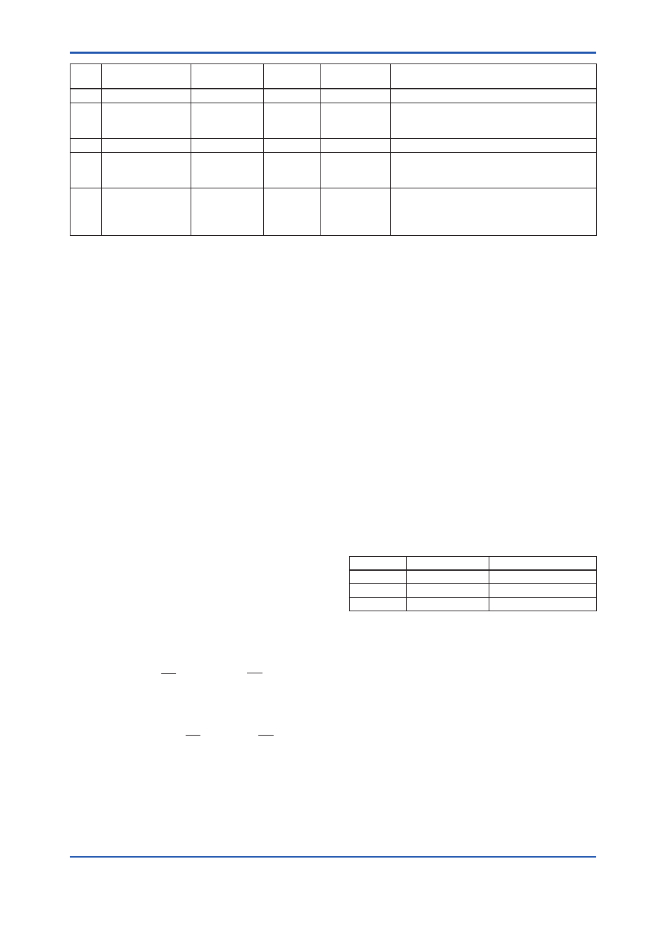
A4.4.2 PID Control Parameters
The table below shows the PID control parameters.
Parameter
Description
Valid Range
GAIN
Proportional gain 0.05 to 20
RESET
Integral time
0.1 to 10,000 (seconds)
RATE
Derivative time
0 to infinity (seconds)
A4.5 Control Output
The final control output value, OUT, is computed
based on the change in control output ΔMVn, which
is calculated at each control period in accordance
with the aforementioned algorithm. The PID block
in a YTA performs the velocity type output action for
the control output.