Yokogawa Wireless Temperature Transmitter YTA510 User Manual
Page 45
<8. Handling Caution>
8-5
IM 01C50T02-01E
Sensor circuit
EEx ia IIC T4
Maximum Voltage (Uo) = 7.7 V
Maximum Current (Io) = 70 mA
Maximum Power (Po) = 140 mW
External Capacitance (Co) = 1.6 µF
External Inductance (Lo) = 7.2 mH
Number of Devices
The number of devices (max. 32) possible on a
fieldbus link depends on factors such as the power
consumption of each device, the type of cable used,
use of repeaters, etc.
C) ATEX Intrinsically Safe “ic”
Caution for ATEX Intrinsically Safe “ic”
Note 1. Model YTA320-F/KN25 temperature
transmitters for potentially explosive
atmospheres:
* Applicable Standard: EN 60079-0: 2009,
EN 60079-0: 2012,
EN 60079-11: 2012
* Type of Protection and Marking:
II 3 G Ex ic IIC T4 Gc
* Ambient Temperature: –30 to 70°C
Ambient Humidity: 0 to 100 %
(No condensation)
* IP Code: IP67
* Overvoltage Category: I
Note 2. Electrical Data
[Supply Input]
Maximum input voltage, Ui = 32Vdc
Effective internal capacitance, Ci = 2.4 nF
Effective internal inductance, Li = 8 µH
[Sensor Output]
Maximum output voltage, Uo = 7.7 V
Maximum output current, Io = 70 mA
Maximum output power, Po = 140 mW
Maximum allowed external capacitance,
Co = 1.6 µF
Maximum allowed external inductance,
Lo = 7.2 mH
• The above parameters apply when one of
the two conditions below is given:
- the total Li of the external circuit
(excluding the cable) is < 1% of the Lo
value or
- the total Ci of the external circuit
(excluding the cable) is < 1% of the Co
value.
• The above parameters are reduced to
50% when both of the two conditions
below are given:
- the total Li of the external circuit
(excluding the cable) is ≥ 1% of the Lo
value and
- the total Ci of the external circuit
(excluding the cable) is ≥ 1% of the Co
value.
• The reduced capacitance of the external
circuit (including cable) shall not be
greater than 1µF for Group IIB and 600nF
for Group IIC.
Note 3. Operation
• Keep strictly the “WARNING” on the label
on the transmitter.
WARNING: POTENTIAL
ELECTROSTATIC
CHARGING HAZARD - SEE USER’S
MANUAL
Note 4. Installation
• Cable glands, adapters and/or blanking
elements shall be of Ex “n”, Ex “e” or Ex
“d” and shall be installed so as to maintain
the specified degree of protection (IP
code) of the equipment.
Note 5. Specific Conditions of Use
• Precautions shall be taken to minimize the
risk from electrostatic discharge of painted
parts.
• The dielectric strength of at least 500 V
a.c. r.m.s between the intrinsically safe
circuits and the enclosure of the Model
YTA series temperature transmitter is
limited only by the overvoltage protection.
• Nonmetallic stickers which include no
information for intrinsic safety can be
applied on the surface of enclosure as
long as each surface area of the sticker is
less than 400 mm
2
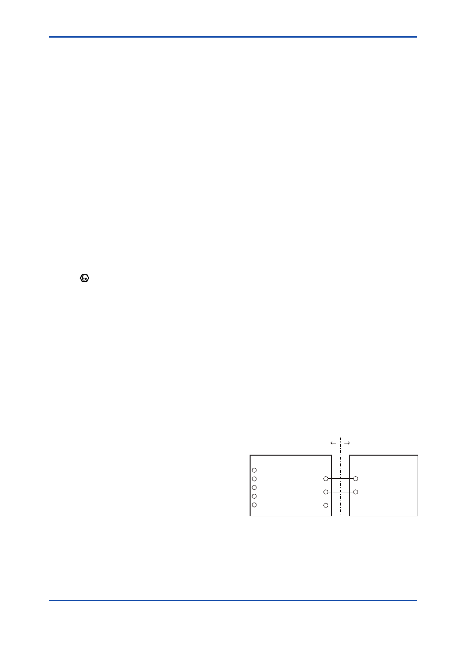
Note 6. Installation Diagram
F0804.ai
Temperature Transmitter
Electrical data are as follows;
Supply Input (Terminals: + and -)
Ui = 32 V
Ci = 2.4 nF
Li = 8 μH
Sensor Output (Terminals: 1 to 5)
Uo = 7.7 V
Io = 70 mA
Po = 140 mW
Co = 1.6 μF
Lo = 7.2 mH
SUPPLY
SUPPLY
SENSOR
Associated Apparatus
Hazardous Area
Non-hazardous Area
+
–
+
–
C
1
2
3
4
5