6 parameters of di function block, 7 a setting when sensor input 2 is not connected, Parameters of di function block -15 – Yokogawa Wireless Temperature Transmitter YTA510 User Manual
Page 28: A setting when sensor input 2 is not connected -15
<5. Configuration>
5-15
IM 01C50T02-01E
PV_FTIME
Stipulates the time constant (in seconds) of the
first-order lag filter inside the AI block.
OUT_SCALE
Stipulates the range of OUT (by setting the
upper and lower range limits). The unit can also
be set freely. OUT_SCALE is set to 0 to 100%
before the YTA320 is shipped from the factory.
Change the setting as necessary.
Alarm Priorities: HI_HI_PRI, HI_PRI, LO_PRI,
and LO_LO_PRI
These parameters determine the respective
priority levels of the four types of process
alarms: HI_HI_ALM, HI_ALM, LO_ALM, and
LO_LO_ALM. Only the alarms whose priority
level is set to 3 or higher will be transmitted
upon occurrence.
These parameters are set to 1 before the
YTA320 is shipped from the factory.
Table 5.18
Alarm Priority
Value
Descriptions
0
Alart is not notified. Alarm parameters are
not updated.
1
Alart is not notified.
3 to 7
Advisory alarms.
8 to 15
Critical alarms.
Alarm Thresholds: HI_HI_LIM, HI_LIM,
LO_LIM, and LO_LO_LIM
These parameters determine the respective
thresholds for the four types of process alarms:
HI_HI_ALM, HI_ALM, LO_ALM, and LO_LO_
ALM. Before the YTA320 is shipped from the
factory, these parameters are set to values such
that no alarm will occur.
5.6.6 Parameters of DI Function Block
Parameters of function blocks can be read and
written from a host computer. See Appendix 1 for
a list of all parameters of the YTA320. This section
describes only the settings for important parameters
of each DI block.
MODE_BLK
Supports O/S, Auto, and Manual modes. The
DI block does not function in the O/S mode,
does not update the measured value in the
Manual mode, and updates the measured
value in the Auto mode. Normally, set the mode
to Auto. Before the YTA320 is shipped from the
factory, all the DI blocks are set to O/S mode.
CHANNEL
Selects the input to the DI block from the
transducer. The table below shows the input
value depending on the setting of CHANNEL.
Set CHANNEL according to the value you want
to input to the DI block.
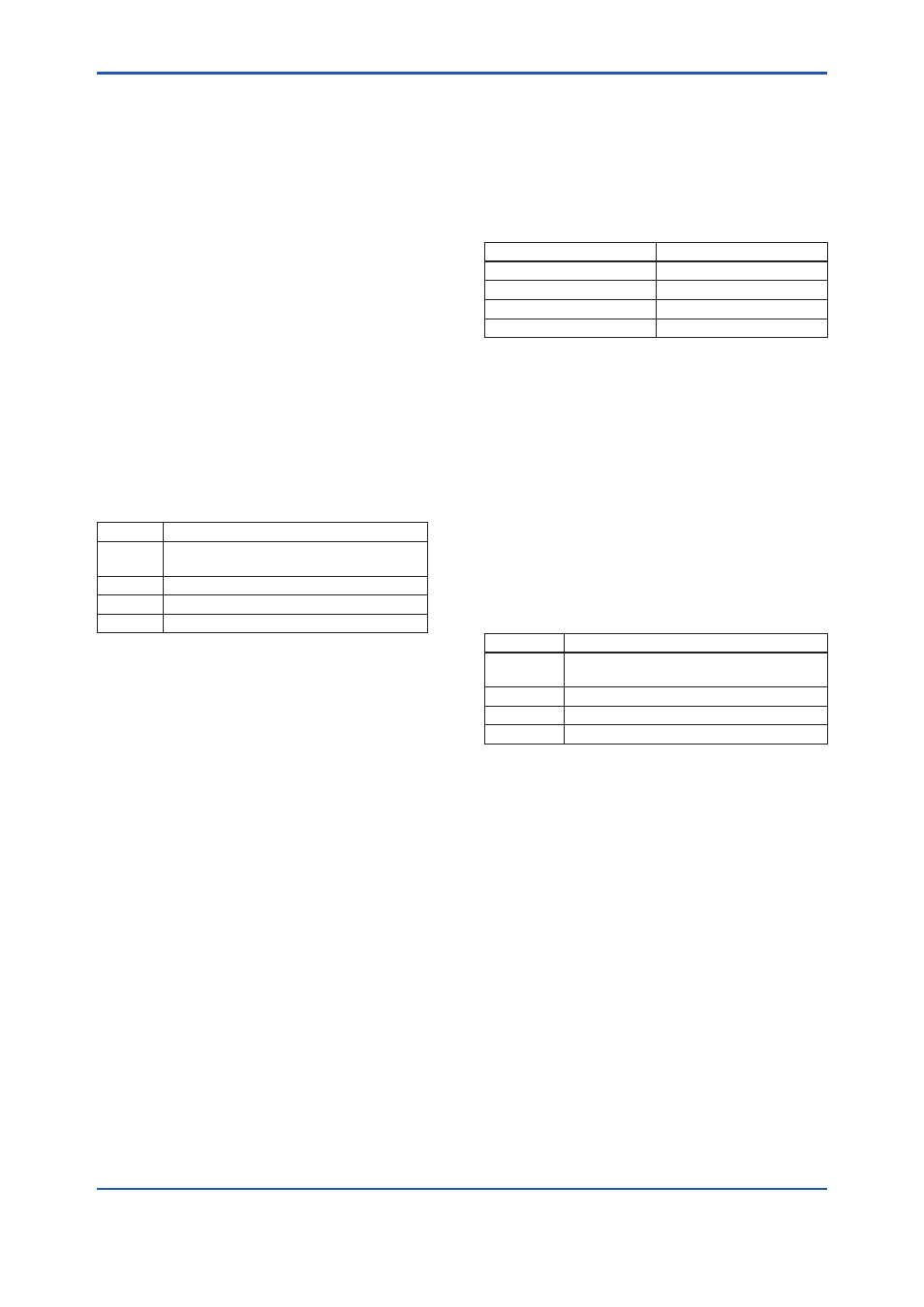
Table 5.19
Input Selected by CHANNEL Setting
CHANNEL Setting
Input Selected
7
Limit switch 1
8
Limit switch 2
9
Limit switch 3
10
Limit switch 4
PV_FTIME
Stipulates the delay time (in seconds) of
changing the output value after a change of the
value inside the DI block.
DISC_PRI
Determines the priority level of the discrete
alarm on the block’s output (OUT_D). The
alarm will be transmitted upon occurrence only
when the DISC_PRI is set at 3 or higher. This
parameter is set to 1 before the YTA320 is
shipped from the factory.
Table 5.20
Alarm Priority
Value
Descriptions
0
Alart is not notified. Alarm parameters are
not updated.
1
Alart is not notified.
3 to 7
Advisory alarms.
8 to 15
Critical alarms.
DISC_LIM
Setpoint of the discrete alarm; when the value
of OUT_D agrees with the value set in DISC_
LIM, the discrete alarm is generated.
5.6.7 A setting when Sensor input 2 is not
connected
When Sensor input 2 is not connected, set
parameters as below.
SENSOR_TYPE_2 (Transducer Block)
Select “Non Connection”.
LIMSW_1(2 to 4)_TARGET (Transducer
Block)
Select “PRIMARY_VALUE_1” or
“SECONDARY_VALUE”.
CHANNEL (AI1 to AI4 function Block)
Set “1” or “3”. “1” means PRIMARY_VALUE_1
and “3” means SECONDARY_VALUE.