A2.2 making and changing basic parameter settings, A2.3 setting up the transducer block, A2.2 – Yokogawa Wireless Temperature Transmitter YTA510 User Manual
Page 71: A2.3, A2-2, Important
A2-2
IM 01C50T02-01E
To Do This
Corresponding Parameters
Outline of Procedure
Set the output cut-off
levels
LOW_CUT
in each AI block
For each AI block, set the output cut-off level suitable for the
L_TYPE setting (= Direct, Indirect, or IndirectSQRT). The
output value will be cut off to 0 when it is below the value set in
LOW_CUT.
Set the time constants
of damping filters
PV_FTIME
of each of AI and DI blocks
For each AI block, set the time constant (in seconds) of the
first-order lag filter.
For each DI block, set the delay time in seconds.
Carry out simulations
for AI and DI blocks
SIMULATE
in each AI block
SIMULATE_D
in each DI block
Manually set input values and statuses for AI and DI blocks;
the blocks then carry out the specified actions with the
simulated input signals. This simulation function is useful for
loop checks and so on. See Section 6.3 for details.
Make LCD display
settings
DISPLAY_AI_OUT
DISPLAY_CYCLE in the
transducer block
Select the AI blocks whose output values you want to display
on the LCD and set the display refresh cycle. If the response
of the LCD is slow such as when used in a cold place, the
display refresh cycle needs to be adjusted.
Carry out an input
calibration
CAL_POINT_HI
CAL_POINT_LO
in the transducer block
Apply an input signal, vary the input signal level, and set the
upper and lower range limits corresponding to the 0% and
100% input levels. The output range can be set accurately
to the exact output signal levels generated by the user's
reference instrument.
A2.2 Making and Changing
Basic Parameter Settings
The figure below outlines the procedure to make
basic parameter settings and change them.
The method of accessing each parameter differs
depending on the configuration tool you use;
see the documentation for the configuration tool.
Access the parameter MODE_BLK in the function block
containing the parameter whose settings you want to
make or change.
Set the target mode(Note 1) in MODE_BLK to a mode
(Auto, Man, or O/S(Note 2)) in which write access to the
desired parameter is permitted.
Access the desired parameter.
Change the settings as appropriate.
Return the target mode in MODE_BLK to Auto. (Note 2)
IMPORTANT
Do not turn off the power to the YTA320
transmitter immediately after changing the
parameter settings.
If the power is turned off within 60 seconds after
making a change, the change is not saved and
the previous setting is restored.
Note 1: MODE_BLK is a universal parameter that indicates the
block operation conditions and is composed of actual
mode, target mode, permitted modes, and normal
mode.
Target: Used to set the mode that the block should
enter.
Actual: Indicates the current mode of the block.
Permit: Indicates all modes that the block can enter.
Normal: Indicates the mode in which the block should
be normally.
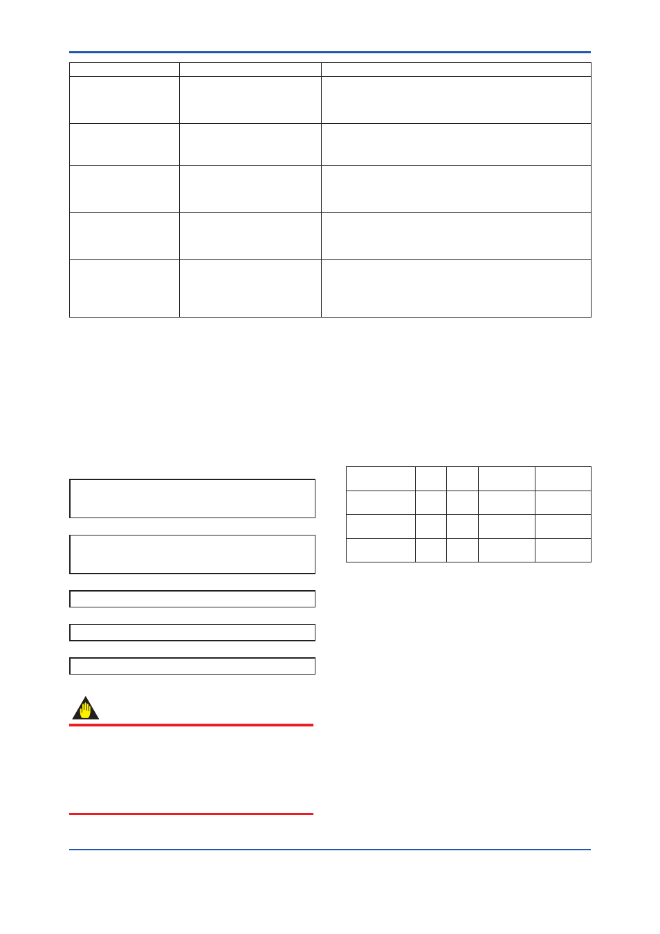
Note 2: The modes each block can enter are as follows.
Mode
AI
Block
DI
Block
Transducer
Block
Resource
Block
AUTO
(automatic)
MAN
(manual)
O/S
(out of service)
For the modes in which each parameter can be
written, see Appendix 1.
A2.3 Setting Up the Transducer
Block
To access the transducer’s functions specific to
the YTA320, the Device Description (DD) for the
YTA320 needs to be installed in the configuration
tool you use. For details on how to install the DD,
see Section 4.4.