2 network definition, Network definition -2 – Yokogawa Wireless Temperature Transmitter YTA510 User Manual
Page 15
<5. Configuration>
5-2
IM 01C50T02-01E
5.2 Network Definition
Before connection of devices with Fieldbus, define
the Fieldbus network. Allocate PD Tag and node
addresses to all devices (excluding such passive
devices as terminators).
The PD Tag is the same as the conventional
one used for the device. Up to 32 alphanumeric
characters may be used for definition. Use a
hyphen as a delimiter as required.
The node address is used to specify devices for
communication purposes. Because data is too long
for a PD Tag, the host uses the node address in
place of the PD Tag for communication. A range of
16 to 247 (or hexadecimal 10 to F7) can be set. The
device (LM device) with bus control function (Link
Master function) is allocated from a smaller address
number (16) side, and other devices (BASIC
device) without bus control function allocated from
a larger address number (247) side respectively.
Place YTA in the range of the BASIC device. When
the YTA is used as Link Master, place YTA in the
range of LM device. Set the range of addresses
to be used to the LM device. Set the following
parameters.
Table 5.1
Parameters for Setting Address Range
Symbol
Parameters
Description
V (FUN) First-Unpolled-
Node
Indicates the address
next to the address
range used for the host
or other LM device.
V (NUN) Number-of-
consecutive-
Unpolled-Node
Unused address range.
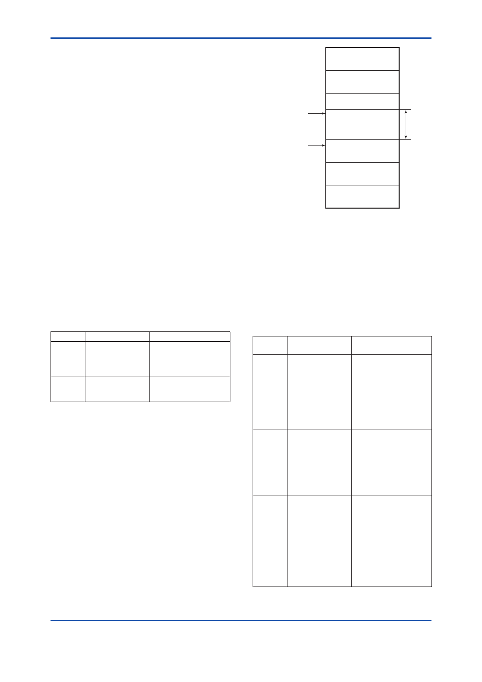
The devices within the address range written
as “Unused” in Figure 5.1 cannot be used on a
Fieldbus. For other address ranges, the range is
periodically checked to identify when a new device
is mounted. Care must be taken not to allow the
address range to become wider, which can lead to
exhaustive consumption of Fieldbus communication
performance.
Bridge device
Not used
0x10
0x00
0x14
0xF7
0xF8
0xFB
0xFC
0xFF
V(FUN)
V(FUN)+V(NUN)
LM device
Unused
V(NUN)
BASIC device
Default address
Portable device address
F0501.ai
Figure 5.1
Available Range of Node Addresses
To ensure stable operation of Fieldbus, determine
the operation parameters and set them to the LM
devices. While the parameters in Table 5.2 are to
be set, the worst-case value of all the devices to
be connected to the same Fieldbus must be used.
Refer to the specification of each device for details.
Table 5.2 lists YTA specification values.
Table 5.2
Operation Parameter Values of the YTA
to be Set to LM Devices
Symbol
Parameters
Description and
Settings
V (ST)
Slot-Time
Indicates the time
necessary for
immediate reply of thje
device. Unit of time is
in octets (256 μs). Set
maximum specification
for all devices. For
YTA, set a value of 4 or
greater.
V (MID)
Minimum-Inter-
PDU-Delay
Minimum value of
communication data
intervals. Unit of time
is in octets (256 μs).
Set the maximum
specification for all
devices. For YTA, set a
value of 4 or greater.
V (MRD) Maximum-Reply-
Delay
The worst case time
elapsed until a reply
is recorded. The
unit is Slot-time; set
the value so that V
(MRD) × V (ST) is the
maximum value of the
specification for all
devices. For YTA, the
setting must be a value
of 12 or greater.