Yokogawa Wireless Temperature Transmitter YTA510 User Manual
Page 49
<8. Handling Caution>
8-9
IM 01C50T02-01E
The allowed voltage Uo of the associated apparatus
used to supply the bus is limited to the range of 14
V dc to 24 V dc. All other equipment connected to
the bus cable has to be passive, meaning that the
apparatus is not allowed to provide energy to the
system, except to a leakage current of 50 µA for
each connected device.
Supply unit
Trapezoidal or rectangular output characteristic only
Uo = 14...24 V (I.S. maximum value)
Io according to spark test result or other
assessment, e.g. 133 mA for Uo = 15 V (Group
IIC, rectangular characteristic) No specification
of Lo and Co in the certificate and on the label.
Cable
The cable used to interconnect the devices needs
to comply with the following parameters:
loop resistance R’: 15...150 Ω/km
inductance per unit length L’: 0.4...1 mH/km
capacitance per unit length C’: 80...200 nF/km
C’=C’ line/line+0.5 C’ line/screen, if both lines
are floating
or
C’=C’ line/line+C’ line/screen, if the screen is
connected to one line
length of spur cable: max. 30 m (Group IIC) or
120 m (Group IIB)
length of trunk cable: max. 1 km (Group IIC) or
1.9 km (Group IIB)
Terminators
At each end of the trunk cable an approved line
terminator with the following parameters is suitable:
R = 90...100 Ω
C = 0...2.2 F
The resistor must be infallible according to IEC
60079-11. One of the two allowed terminators might
already be intergrated in the associated apparatus
(bus supply unit)
System evaluations
The number of passive device like transmitters,
actuators, hand held terminals connected to
a single bus segment is not limited due to I.S.
reasons. Furthermore, if the above rules are
respected, the inductance and capacitance of the
cable need not to be considered and will not impair
the intrinsic safety of the installation.
SAFE AREA
HAZARDOUS AREA
F0808.ai
Terminator
(FISCO Model)
Ex i
Field Instruments
(Passive)
Hand-
held-
Terminal
Supply Unit
(FISCO Model)
Terminator
Data
U
U
I
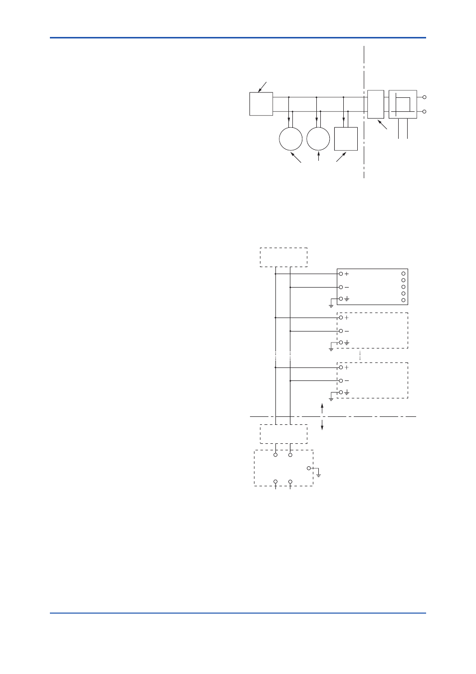
I.S. fieldbus system complying with FISCO model
Installation Diagram
(Nonincendive, Division 2 Installation)
Non Hazardous Location
Hazardous Location
F0809.ai
Terminator
Transmitter
Temperature
Transmitter
Terminator
Transmitter
1
2
3
4
5
SUPPLY
FM Approved Associated
Nonincendive Field Wiring Apparatus
Vt or Voc
It or Isc
Ca
La
(Nonincendive)
Power Supply
SENSOR
*1:
Dust-tight conduit seal must be used when installed in
Class II and Class III environments.
*2:
Installation should be in accordance with and the National
Electrical Code® (ANSI/NFPA 70) Sections 504 and 505.
*3:
The configuration of Associated Nonincendive Field
Wiring Apparatus must be FM Approved.