Yokogawa Wireless Temperature Transmitter YTA510 User Manual
Page 51
<8. Handling Caution>
8-11
IM 01C50T02-01E
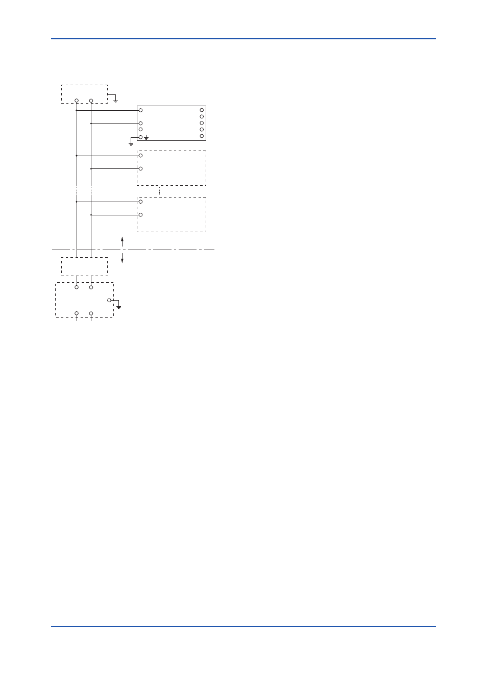
Installation Diagram
(Installation Diagram for Intrinsically
Safe)
Non Hazardous Location
Hazardous Location
F0810.ai
Terminator
Safety Barrier
Temperature
Transmitter
Terminator
+
–
Transmitter
+
–
Transmitter
+
–
1
2
3
4
5
SUPPLY
C(*)
+
–
+
–
SENSOR
(*)‘C’ and ‘–’ may be shorted.
Note
• In the rating 1 (*1), the output current of the
barrier must be limited by a resistor ‘Ra’such
that Io=Uo /Ra.
• In the rating 2 (*2), the output of the barrier must
be the characteristics of the trapezoid or the
rectangle and this transmitter can be connected
to Fieldbus equipment which are in according to
the FISCO model.
• The safely barrier may include a terminator.
• The terminator may be built in by a barrier.
• The terminator and the safety barrier must be
certified by Ex certification bodies.
• More than one field instruments may be
connected to the power supply line.
• Do not alter drawing without authorization from
Ex certification bodies.
• Input voltage of the safety barrier must be less
than 250Vrms/V dc.
Electrical Data:
• Supply Input (+ and –)
Maximum Input Voltage Ui: 24 V *
1
Maximum Input Current Ii: 250 mA *
1
Maximum Input Power Pi: 1.2 W *
1
Maximum Internal Capacitance Ci: 1.5 nF *
1
Maximum Internal Inductance Li: 8 µH *
1
or
Maximum Input Voltage Ui: 17.5 V *
2
Maximum Input Current Ii: 360 mA *
2
Maximum Input Power Pi: 2.52 W *
2
Maximum Internal Capacitance Ci: 1.5 nF *
2
Maximum Internal Inductance Li: 8 µH *
2
or
Maximum Input Voltage Ui: 17.5 V *
2
Maximum Input Current Ii: 380 mA *
2
Maximum Input Power Pi: 5.32 W *
2
Maximum Internal Capacitance Ci: 1.5 nF *
2
Maximum Internal Inductance Li: 8 µH *
2
• Sensor Output (1 to 5)
Maximum Output Voltage Uo: 7.7 V
Maximum Output Current Io: 70 mA
Maximum Output Power Po: 140 mW
Maximum External Capacitance Co: 1.6 µF
Maximum External Inductance Lo: 7.2 mH
FISCO Rules
The FISCO Concept allows the interconnection
of intrinsincally safe apparatus to associated
apparatus not specifically examined in such
combination. The criterion for such interconnection
is that the voltage (Ui), the current (Ii) and the
power (Pi) which intrinsically safe apparatus can
receive and remain intrinsically safe, considering
faults, must be equal or greater than the voltage
(Uo, Voc, Vt), the current (Io) and the power (Po)
which can be provided by the associated apparatus
(supply unit). In addition, the maximum unprotected
residual capacitance (Ci) and inductance (Li)
of each apparatus (other than the terminators)
connected to the fieldbus must be less than or
equal to 5 nF and 10 µH respectively.
In each I.S. fieldbus segment only one active
source, normally the associated apparatus, is
allowed to provide the necessary power for the
fieldbus system. The allowed voltage Uo of the
associated apparatus used to supply the bus
is limited to the range of 14 V dc to 24 V dc. All
other equipment connected to the bus cable has
to be passive, meaning that the apparatus is not
allowed to provide energy to the system, except
to a leakage current of 50 µA for each connected
device.