Yokogawa Wireless Temperature Transmitter YTA510 User Manual
Page 43
<8. Handling Caution>
8-3
IM 01C50T02-01E
* When combined with FISCO model IIC
barrier
Ui = 17.5 V, Ii = 360 mA, Pi = 2.52 W,
Ci = 1.5 nF, Li = 8 µH
* When combined with barrier
Ui = 24.0 V, Ii = 250 mA, Pi = 1.2 W,
Ci = 1.5 nF, Li = 8 µH
• EEx ia IIB T4
Type of Protection and Marking Code:
EEx ia IIB T4
Group: II
Category: 1G
Ambient Temperature: –40 to 60°C
Degree of Protection of the Enclosure: IP67
Electrical Data
* When combined with FISCO model IIB
barrier
Ui = 17.5 V, Ii = 380 mA, Pi = 5.32 W,
Ci = 1.5 nF, Li = 8 µH
[Sensor circuit]
Uo = 7.7 V, Io = 70 mA, Po = 140 mW,
Co = 1.6 µF, Li = 7.2 mH
• The above parameters apply when one of
the two conditions below is given:
- the total Li of the external circuit
(excluding the cable) is < 1% of the Lo
value or
- the total Ci of the external circuit
(excluding the cable) is < 1% of the Co
value.
• The above parameters are reduced to
50% when both of the two conditions
below are given:
- the total Li of the external circuit
(excluding the cable) is ≥ 1% of the Lo
value and
- the total Ci of the external circuit
(excluding the cable) is ≥ 1% of the Co
value.
• The reduced capacitance of the external
circuit (including cable) shall not be
greater than 1µF for Group IIB and 600nF
for Group IIC.
Note 3. Installation
* All wiring shall comply with local
installation requirements. (Refer to the
installation diagram)
Note 4. Maintenance and Repair
* The instrument modification or parts
replacement by other than authorized
representative of Yokogawa Electric
Corporation is prohibited and will void
KEMA Intrinsically safe Certification.
Note 5. Special condition for safe use
* Because the enclosure of the Temperature
Transmitter is made of aluminum, if it
is mounted in an area where the use of
category 1G apparatus is required, it must
be installed such, that, even in the event
of rare incidents, ignition source due to
impact and friction sparks are excluded.
Note 6. Installation instructions
* From the safety point of view the circuit
shall be considered to be connected to
earth.
As this deviates from the FISCO system
in accordance with IEC TS 60079-27 care
has to be taken that the (local) installation
requirements are taken into account as
well.
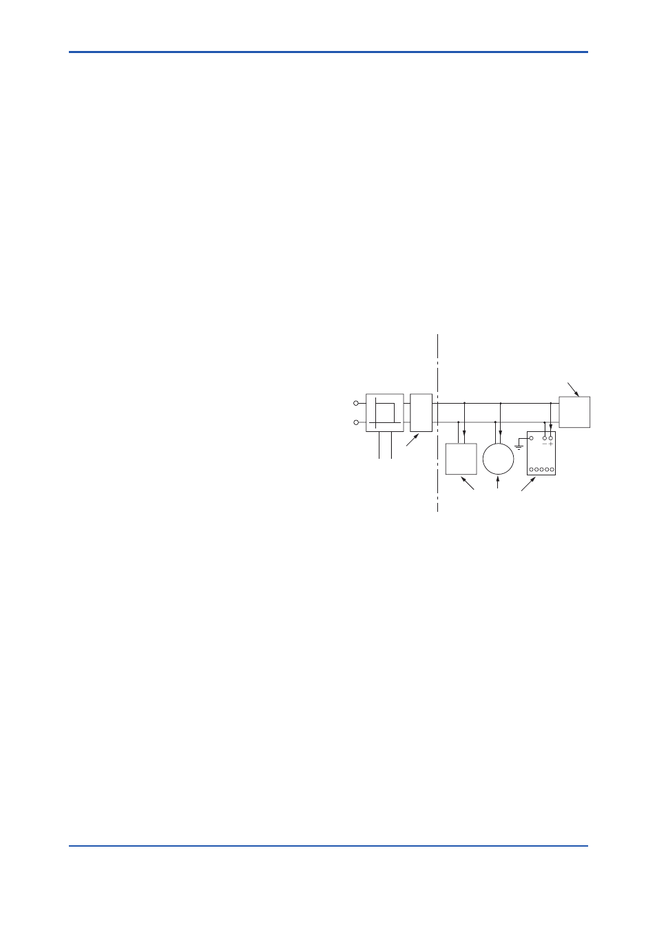
(1) FISCO Model
Non-Hazardous
Locations
Hazardous Locations
F0802.ai
Terminator
(FISCO Model)
Ex i
Field Instruments
(Passive)
Hand-
held-
Terminal
Supply Unit
(FISCO Model)
Terminator
Data
U
U
I
YTA
1 23 45
Supply
Sensor
I.S. fieldbus system complying with FISCO
The criterion for such interconnection is that the
voltage (Ui), the current (Ii) and the power (Pi),
which intrinsically safe apparatus can receive,
must be equal or greater than the voltage (Uo),
the current (Io) and the power (Po) which can be
provided by the associated apparatus (supply unit).
In addition, the maximum unprotected residual
capacitance (Ci) and inductance (Li) of each
apparatus (other than the terminators) connected
to the fieldbus line must be equal or less than 5 nF
and 10 µH respectively.