3 simulation function, 4 operation of integral indicator, Simulation function -2 – Yokogawa Wireless Temperature Transmitter YTA510 User Manual
Page 30: Operation of integral indicator -2
<6. In-process Operation>
6-2
IM 01C50T02-01E
Table 6.1
Alert Object
Subindex
Parameter
Name
Explanation
A
na
lo
g
A
le
rt
D
is
cr
et
e
A
le
rt
U
pd
at
e
A
le
rt
1
1
1
Block
Index
Index of block from
which alert is generated
2
2
2
Alert Key
Alert Key copied from
the block
3
3
3
Standard
Type
Type of the alert
4
4
4
Mfr Type
Alert Name identified by
manufacturer specific
DD
5
5
5
Message
Type
Reason of alert
notification
6
6
6
Priority
Priority of the alarm
7
7
7
Time
Stamp
Time when this alert is
first detected
8
8
Subcode
Enumerated cause of
this alert
9
9
Value
Value of referenced data
10
10
Relative
Index
Relative index of
referenced data
8
Static
Revision
Value of static revision
(ST_REV) of the block
11
11
9
Unit Index Unit code of referenced
data
6.3 Simulation Function
The simulation function simulates the input of a
function block and lets it operate as if the data was
received from the transducer block. It is possible to
conduct testing for the downstream function blocks
or alarm processes.
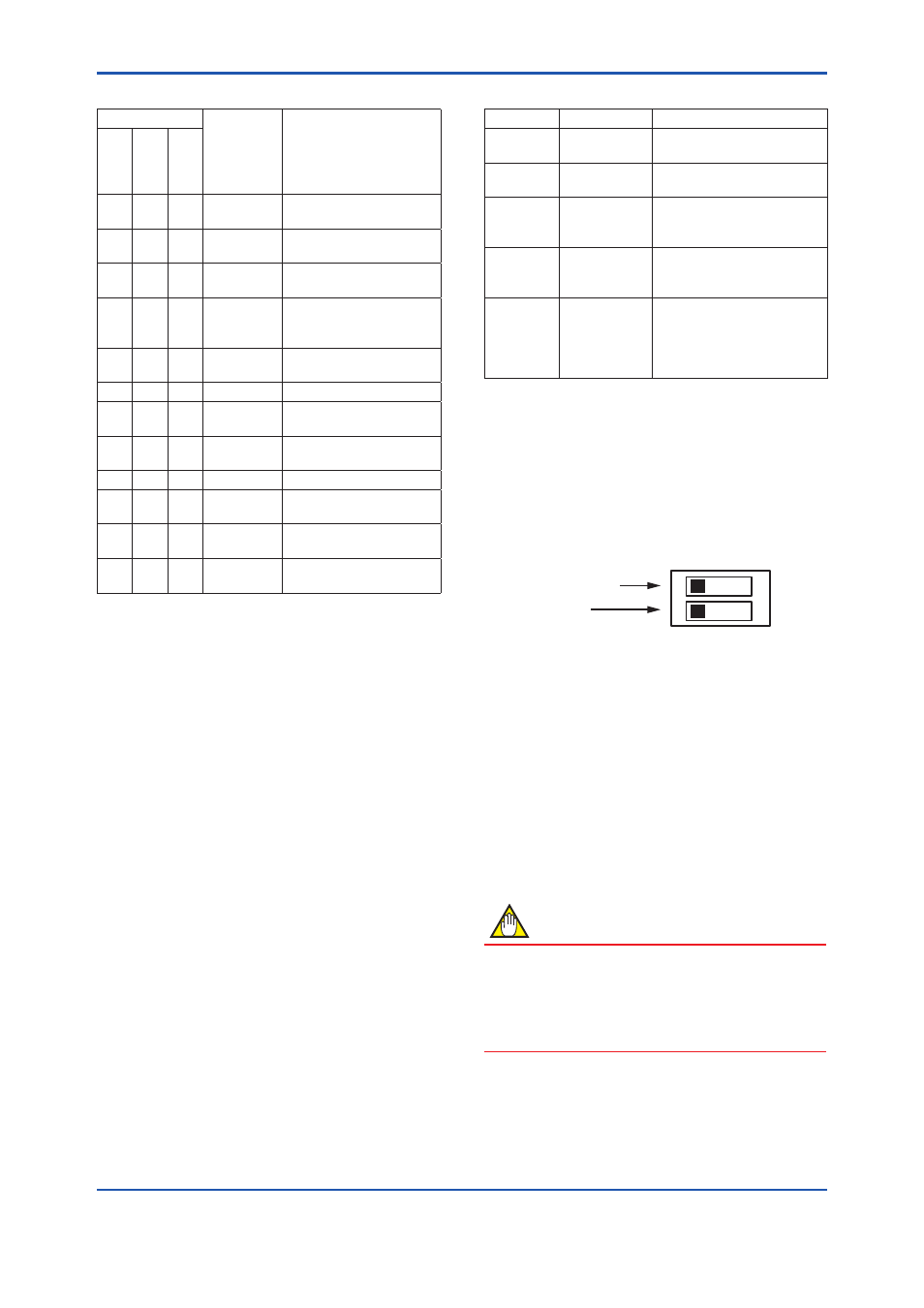
A SIMULATE_ENABLE switch is mounted in the
YTA amplifier. This is to prevent the accidental
operation of this function. When this is switched
on, simulation is enabled. (See Figure 6.2.) To
initiate the same action from a remote terminal,
if REMOTE LOOP TEST SWITCH (Note: in
capital letter) is written to the SIM_ENABLE_MSG
parameter (index 1044) of the resource block, the
resulting action is the same as is taken when the
above switch is on. Note that this parameter value
is lost when the power is turned OFF. In simulation
enabled status, an alarm is generated from the
resource block, and other device alarms will be
masked; for this reason the simulation must be
disabled immediately after using this function.
The SIMULATE parameter of AI block consists of
the elements listed in Table 6.2 below.
Table 6.2
SIMULATE(_D) Parameter
Subindex Parameters
Description
1
Simulate
Status
Sets the data status to be
simulated.
2
Simulate
Value
Sets the value of the data
to be simulated.
3
Transducer
Status
Displays the data status
from the transducer block.
It cannot be changed.
4
Transducer
Value
Displays the data value
from the transducer block.
It cannot be changed.
5
Simulate
En/Disable
Controls the simulation
function of this block.
1: Simulation disabled
(standard)
2: Simulation started
When Simulate En/Disable in Table 6.2 above is
set to 2, the applicable function block uses the
simulation value set in this parameter instead of
the data from the transducer block. This setting can
be used for propagation of the status to the trailing
blocks, generation of a process alarm, and as an
operation test for trailing blocks.
F0602.ai
1
2
O
N
"OFF" during operation
Not in use
SIM. ENABLE
Figure 6.2
SIMULATE_ENABLE Switch Position
6.4 Operation of Integral
Indicator
If integral indicator is specified, the LCD display
which can diplay output value of each AI block,
address and error codes is installed with the
instrument. Items to be displayed can be selected
in Transducer block parameters. (Refer to section
5.6.4.)
NOTE
Though the DISPLAY_WARNING parameter
is set to "SHOW", code for warning will not
be shown if the warning function is disabled
by parameters WARNING_ENABLE _# in
Transducer block.