A2.1 basic settings and corresponding parameters, A2.1, A2-1 – Yokogawa Wireless Temperature Transmitter YTA510 User Manual
Page 70
A2-1
IM 01C50T02-01E
Appendix 2. Parameters for Basic
Settings, and How to Make
and Change the Settings
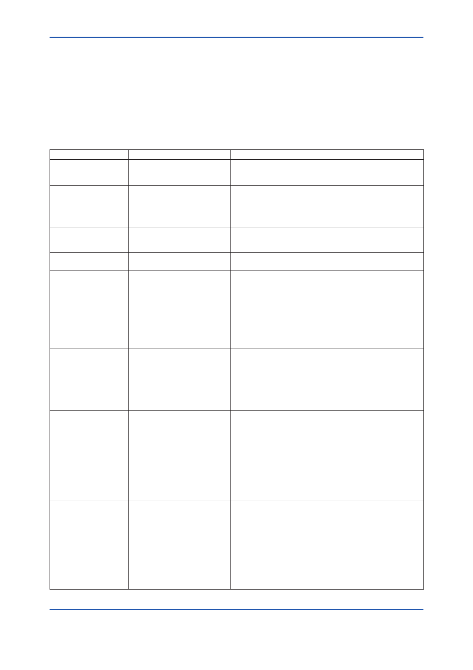
A2.1 Basic Settings and Corresponding Parameters
To Do This
Corresponding Parameters
Outline of Procedure
Set the tag numbers
—
Set the physical device tag number and each block's tag
number. Up to 32 alphanumeric characters can be set for
each. See Section 5.4 for details.
Make input sensor
settings
SENSOR_TYPE_1
SENSOR_CONNECTION_1
SENSOR_TYPE_2
SENSOR_CONNECTION_2
in the transducer block
Select the input sensor type and set the number of connection
wires, for each of sensors 1 and 2.
Set up a limit switch
LIMSW_1_TARGET
LIMSW_1_SETPOINT
in the transducer block
For limit switch 1, select the temperature to be monitored,
select the switch type (high-limit or low-limit switch), and set
the hysteresis and threshold.
Select inputs to AI and
DI blocks
CHANNEL
in each of AI and DI blocks
Select an output of the transducer block to be input to each of
the AI and DI blocks.
Set the measurement
ranges
XD_SCALE
in each AI block
For each AI block, set the range of the input from the
transducer block corresponding to 0% and 100% input levels
for the calculation inside the AI block. Before the transmitter is
shipped from the factory, these input range limits are set to the
0% and 100% range values specified by the customer when
ordered.
Set 3 data items: the unit of the input range, input value at 0%
input level (lower limit of calibrated range), and input value at
100% input level (upper limit of calibrated range).
Set output scales and
unit
OUT_SCALE
in each AI block
For each AI block, set the output scale corresponding to 0%
and 100% output levels for the calculation inside the AI block.
A different unit and range from those of the calibrated range
can be set by using the scaling calculation inside the block.
Set 3 data items: the unit of the output scale, output value at
0% output level (lower output scale limit), and output value at
100% output level (upper output scale limit).
Set the scale range and
unit of built-in indicator
[L_TYPE= Indirect/Indirect
SQRT]
OUT_SCALE
in the AI block or each of the AI
blocks whose outputs are to be
indicated
[L_TYPE= Direct]
XD_SCALE
In the AI block or each of the AI
blocks whose outputs are to be
indicated
When output mode L_TYPE is set to Indirect or Indirect
SQRT, the scales and units set in OUT_SCALE's above apply
to those of the indicator.
When output mode L_TYPE is set to Direct, the scales and
units set in XD_SCALE's above apply to those of the indicator.
The value to be displayed is within a range from −9999.9 to
9999.9.
Set the output modes
L_TYPE
in each AI block
Select the type of calculation performed in each AI block from
the following.
Direct: Outputs the value input from the transducer block
through filtering without performing the scaling and
square root extraction.
Indirect: Performs proportional scaling for the value input
from the transducer block through filtering, and then
outputs the result.
IndirectSQRT: Extracts the square root of the value input
from the transducer block through filtering, and then
outputs it.