2 host setting, 3 bus power on, Host setting -2 – Yokogawa Wireless Temperature Transmitter YTA510 User Manual
Page 12: Bus power on -2, Important
<4. Getting Started>
4-2
IM 01C50T02-01E
4.2 Host Setting
To activate Fieldbus, the following settings are
required for the host.
IMPORTANT
Do not turn off the power immediately after
setting. When the parameters are saved to
EEPROM, the redundant processing is executed
for the improvement of reliability. If the power
is turned off within 60 seconds after setting is
made, the modified parameters are not saved
and the settings may return to the original values.
Table 4.1
Operation Parameters
Symbol
Parameter
Description and
Settings
V (ST)
Slot-Time
Set 4 or greater value.
V (MID)
Minimum-Inter-
PDU-Delay
Set 4 or greater value.
V (MRD) Maximum-
Response-Delay
Set so that V (MRD) ×
V (ST) is 12 or greater
V (FUN) First-Unpolled-
Node
Indicate the address
next to the address
range used by the host.
Set 0x15 or greater.
V (NUN) Number-of-
consecutive-
Unpolled-Node
Unused address range.
YTA address is factory-
set to 0xF3. Set this
address to be within
the range of the BASIC
device in Figure 4.2.
Bridge device
Not used
0x10
0x00
0x14
0xF7
0xF8
0xFB
0xFC
0xFF
V(FUN)
V(FUN)+V(NUN)
YTA(0xF3)
LM device
Unused
V(NUN)
BASIC device
Default address
Portable device address
F0402.ai
Note 1: LM device: with bus control function (Link Master
function)
Note 2: BASIC device: without bus control function
Figure 4.2
Available Address Range
4.3 Bus Power ON
Turn on the power of the host and the bus. Where
the YTA is equipped with an LCD indicator, first all
segments are lit, then the display begins to operate.
If the indicator is not lit, check the polarity of the
power supply.
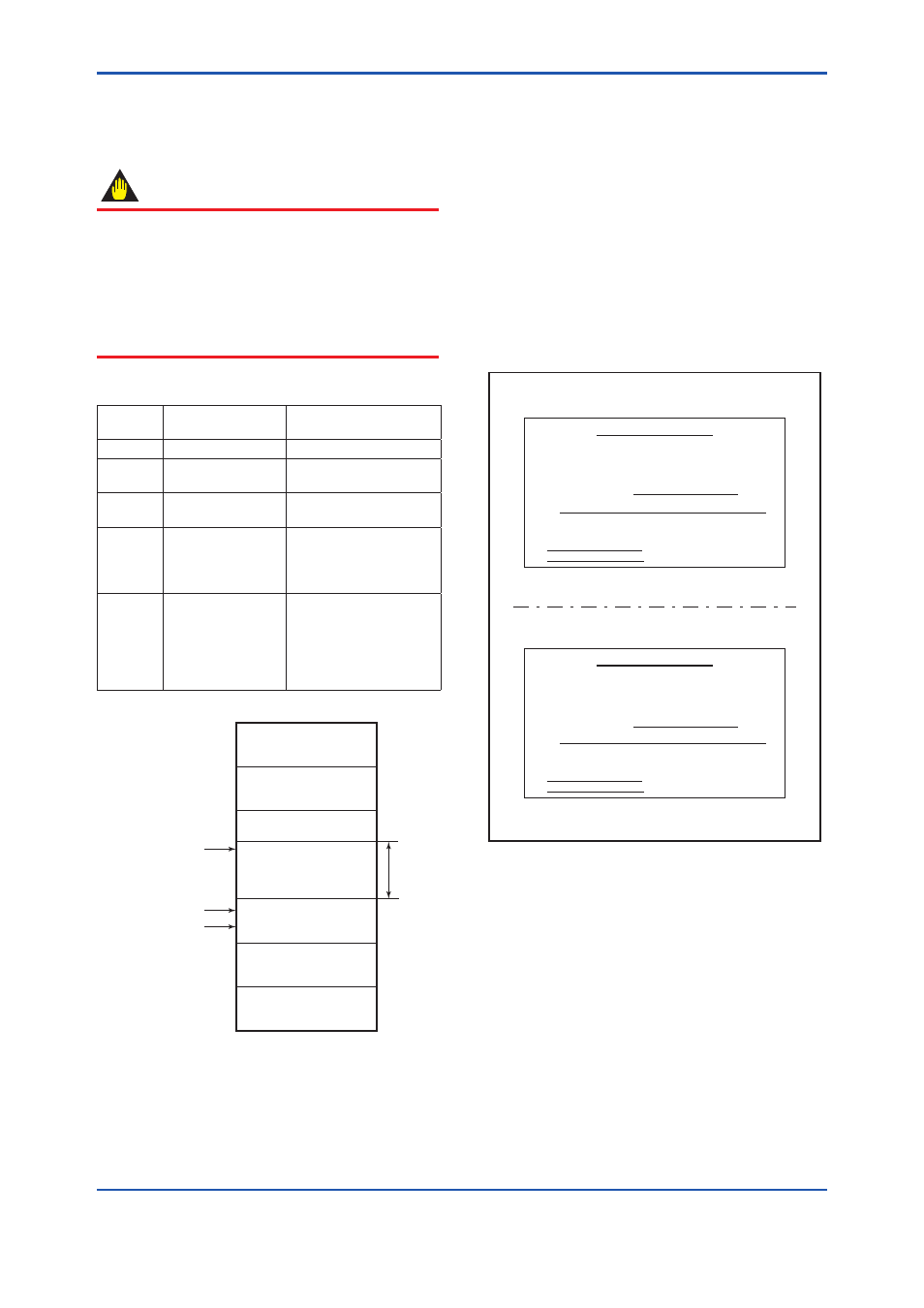
Using the host device display function, check that
the YTA is in operation on the bus.
The device information, including PD tag, Node
address, and Device ID, is described on the
sheet attached to YTA. The duplicates of device
information are provided on this sheet.
DEVICE INFORMATION
Device ID
:
5945430005XXXXXXXX
PD Tag
:
TT1001
Device Revision
:
X
Node Address
:
0xf3
Serial No.
:
XXXXXXXXXXXXXXXXX
Physical Location :
Note:
Our Device Description Files and Capabilities Files available at
http://www.yokogawa.com/fld/ (English) or
http://www.yokogawa.co.jp/fld/ (Japanese)
F0403.ai
Figure 4.3
Device Information Sheet Attached to
YTA
If no YTA is detected, check the available address
range and the polarity of the power supply. If the
node address and PD tag are not specified when
ordering, default value is factory set. If two or more
YTAs are connected at a time with default value,
one YTA will keep the address upon shipment while
the other will have a default address as they have
the same initial addres. Separately connect each
YTA and set a different address for each.