Yokogawa Wireless Temperature Transmitter YTA510 User Manual
Page 48
<8. Handling Caution>
8-8
IM 01C50T02-01E
IFM018-A12
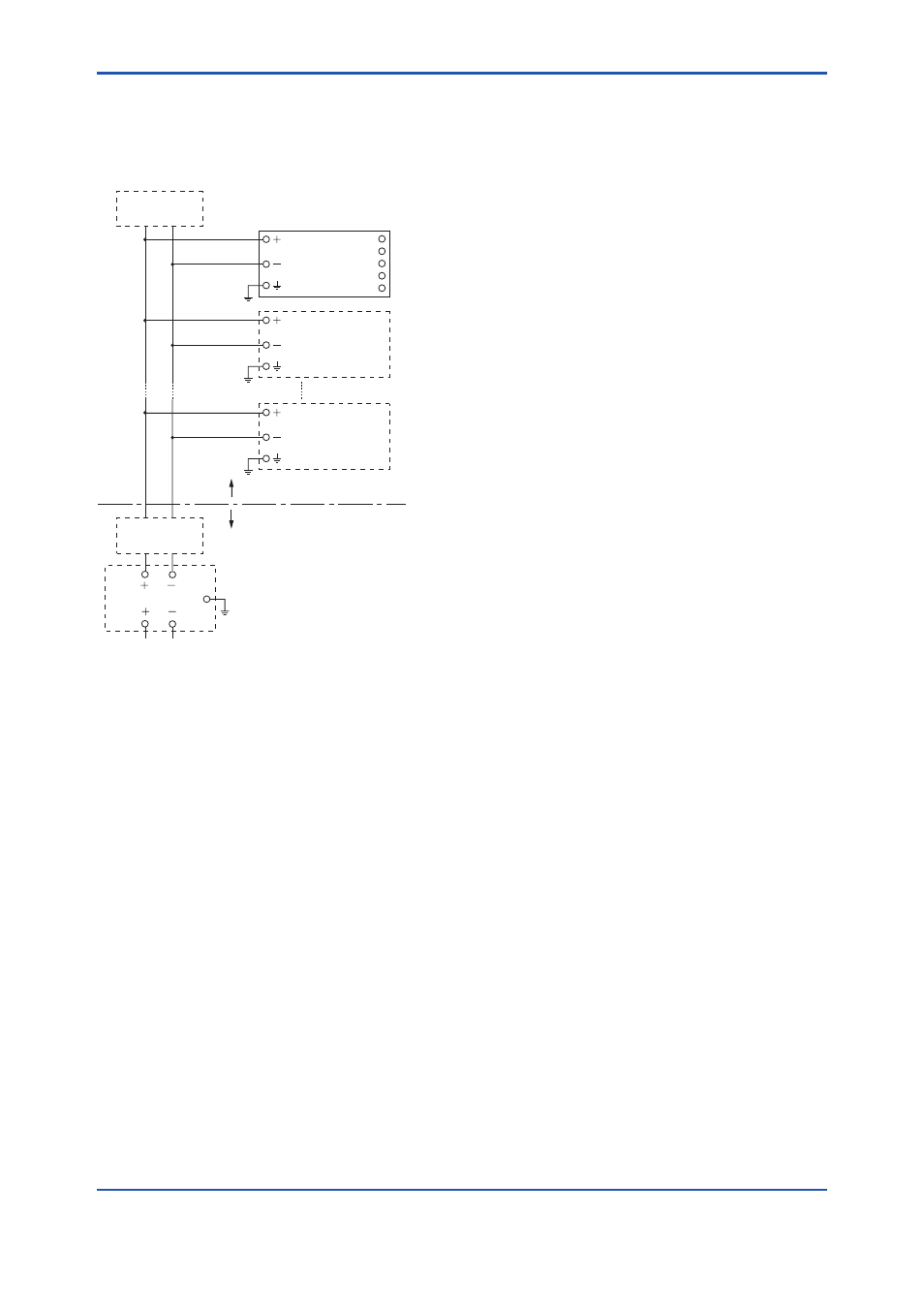
Installation Diagram
(Intrinsically safe, Division 1 Installation)
Non Hazardous Location
Hazardous Location
F0807.ai
Terminator
Transmitter
Safety Barrier
Temperature
Transmitter
Terminator
Transmitter
1
2
3
4
5
SUPPLY
SENSOR
*1:
Dust-tight conduit seal must be used when installed in
Class II and Class III environments.
*2:
Control equipment connected to the Associated Apparatus
must not use or generate more than 250 Vrms or Vdc.
*3:
Installation should be in accordance with ANSI/ISA
RP12/6 “Installation of Intrinsically Safe Systems for
Hazardous (Classified) Locations” and the National
Electrical Code (ANSI/NFPA 70) Sections 504 and 505.
*4:
The configuration of Associated Apparatus must be
Factory Mutual Research Approved under FISCO
Concept.
*5:
Associated Apparatus manufacturer’s installation drawing
must be followed when installing this equipment.
*6:
The YTA Series are approved for Class I, Zone 0,
applications. If connecting AEx (ib) associated Apparatus
or AEx ib I.S. Apparatus to the Zone 2, and is not suitable
for Class I, Zone 0 or Class I, Division 1, Hazardous
(Classified) Locations.
*7:
No revision to drawing without prior Factory Mutual
Research Approval.
*8:
Terminator must be FM Approved.
Electrical Data:
• Rating 1 (Entity and nonincendive)
For Groups A, B, C, D, E, F, and G or Group IIC
Maximum Input Voltage Vmax: 24 V
Maximum Input Current Imax: 250 mA
Maximum Input Power Pi: 1.2 W
Maximum Internal Capacitance Ci: 1.5 nF
Maximum Internal Inductance Li: 8 µH
or
• Rating 2 (FISCO)
For Groups A, B, C, D, E, F, and G or Group IIC
Maximum Input Voltage Vmax: 17.5 V
Maximum Input Current Imax: 360 mA
Maximum Input Power Pi: 2.52 W
Maximum Internal Capacitance Ci: 1.5 nF
Maximum Internal Inductance Li: 8 µH
or
• Rating 3 (FISCO)
For Groups C, D, E, F, and G or Group IIB
Maximum Input Voltage Vmax: 17.5 V
Maximum Input Current Imax: 380 mA
Maximum Input Power Pi: 5.32 W
Maximum Internal Capacitance Ci: 1.5 nF
Maximum Internal Inductance Li: 8 µH
and
• Rating 4 (Sensor circuit)
Maximum Output Voltage Uo: 6.7 V
Maximum Output Current Io: 60 mA
Maximum Output Power Po: 100 mW
Maximum External Capacitance Co: 10 µF
Maximum External Inductance Lo: 10 µH
Note: In the rating 1, the output current of the barrier must be
limited by a resistor “Ra” such that Io=Uo/Ra. In the rating
2 or 3, the output characteristics of the barrier must be the
type of trapezoid which are certified as the FISCO model
(See “FISCO Rules”). The safety barrier may include
a terminator. More than one field instruments may be
connected to the power supply line.
FISCO Rules
The FISCO Concept allows the interconnection
of intrinsincally safe apparatus to associated
apparatus not specifically examined in such
combination. The criterion for such interconnection
is that the voltage (Ui), the current (Ii) and the power
(Pi) which intrinsically safe apparatus can receive
and remain intrinsically safe, considering faults,
must be equal or greater than the voltage (Uo, Voc,
Vt), the current (Io) and the power (Po) which can
be provided by the associated apparatus (supply
unit). In addition, the maximum unprotected residual
capacitance (Ci) and inductance (Li) of each
apparatus (other than the terminators) connected to
the fieldbus must be less than or equal to 5 nF and
10 µH respectively.
In each I.S. fieldbus segment only one active
source, normally the associated apparatus, is
allowed to provide the necessary power for the
fieldbus system.