Getting started, 1 connection of devices, Getting started -1 – Yokogawa Wireless Temperature Transmitter YTA510 User Manual
Page 11: Connection of devices -1, Important
<4. Getting Started>
4-1
IM 01C50T02-01E
4. Getting Started
Fieldbus is fully dependent upon digital
communication protocol and differs in operation
from conventional 4 to 20 mA transmission and
the BRAIN or HART communication protocol. It is
recommended that novice users use field devices
in accordance with the procedures described in this
section. The procedures assume that field devices
will be set up on a bench or an instrument shop.
4.1 Connection of Devices
The following instruments are required for use with
Fieldbus devices:
• Power supply:
Fieldbus requires a dedicated power supply. It
is recommended that current capacity be well
over the total value of the maximum current
consumed by all devices (including the host).
Conventional DC current cannot be used as is.
• Terminator:
Fieldbus requires two terminators. Refer to
the supplier for details of terminators that are
attached to the host.
• Field devices:
Connect Fieldbus communication type YTA320.
Two or more YTA320 devices or other devices
can be connected.
• Host:
Used for accessing field devices. A
dedicated host (such as DCS) is used for
an instrumentation line while dedicated
communication tools are used for experimental
purposes. For operation of the host, refer to
the instruction manual for each host. No details
of the host are explained in the rest of this
material.
• Cable:
Used for connecting devices. Refer to “Fieldbus
Technical Information” (TI 38K3A01-01E) for
details of instrumentation cabling. If the total
length of the cable is in a range of 2 to 3 meters
for laboratory or other experimental use, the
following simplified cable (a twisted pair wire
with a cross section of 0.9 mm2 or more and
cycle period of within 5 cm (2 inches) may be
used. Termination processing depends on the
type of device being deployed. For YTA, use an
M4 screw terminal claw. Some hosts require a
connector.
Refer to Yokogawa when making arrangements to
purchase the recommended equipment.
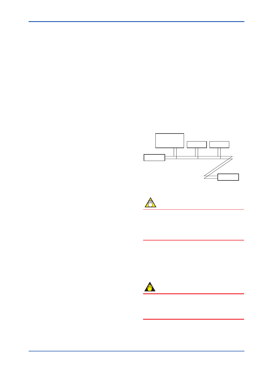
Connect the devices as shown in Figure 4.1.
Connect the terminators at both ends of the
trunk, with a minimum length of the spur laid for
connection.
The polarity of signal and power must be
maintained.
YTA320
Fieldbus power
supply
Terminator
Terminator
HOST
F0401.ai
Figure 4.1
Cabling
NOTE
No CHECK terminal is used for Fieldbus
communication YTA. Do not connect the field
indicator and check meter. Use the instrument
with the short-bar being installed between (-)
terminal and the CHECK terminal.
Before using a Fieldbus configuration tool other
than the existing host, confirm it does not affect the
loop functionality in which all devices are already
installed in operation. Disconnect the relevant
control loop from the bus if necessary.
IMPORTANT
Connecting a Fieldbus configuration tool to a loop
with its existing host may cause communication
data scrambles resulting in a functional disorder
or a system failure.