3 definition of combining function blocks, Definition of combining function blocks -3 – Yokogawa Wireless Temperature Transmitter YTA510 User Manual
Page 16
<5. Configuration>
5-3
IM 01C50T02-01E
5.3 Definition of Combining
Function Blocks
The input/output parameters for function blocks
are combined. For the YTA, four AI blocks output
parameter (OUT), four DI blocks output parameter
(OUT_D) and PID block are subject to combination.
They are combined with the input of the control
block as necessary. Practically, setting is written to
the YTA link object with reference to “Block setting”
in Section 5.6 for details. It is also possible to read
values from the host at proper intervals instead of
connecting the YTA block output to other blocks.
The combined blocks need to be executed
synchronously with other blocks on the
communications schedule. In this case, change
the YTA schedule according to the following table.
Enclosed values in the table are factory-settings.
Table 5.3
Execution Schedule of the YTA
Function Blocks
Index
Parameters
Setting (Enclosed is
factory-setting)
269
(SM)
MACROCYCLE_
DURATION
Cycle (MACROCYCLE)
period of control or
measurement. Unit is
1/32 ms. (16000 = 0.5 s)
276
(SM)
FB_START_ENTRY.1 AI1 block startup time.
Elapsed time from the
start of MACROCYCLE
specified in 1/32 ms.
(0 = 0 s)
277
(SM)
FB_START_ENTRY.2 AI2 block startup time.
Elapsed time from the
start of MACROCYCLE
specified in 1/32 ms.
(4000 = 125 ms)
278
to
285
(SM)
FB_START_ENTRY.3
to
FB_START_ENTRY.10
Not used.
A maximum of 50 ms is taken for execution of each
AI block. A maximum of 30 ms is taken for execution
of each DI block, and 100ms for each PID block.
For scheduling of communications for combination
with the next function block, the execution is so
arranged as to start after a lapse of longer than 100
ms. In no case should function blocks of the YTA
be executed at the same time (execution time is
overlapped).
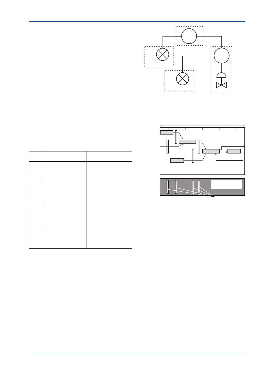
Figure 5.3 shows an example of schedule based on
the loop shown in Figure 5.2.
F0502.ai
TIC100
TC200
TV200
TT 200
YTA
#2
TT100
YTA
#1
Figure 5.2
Example of Loop Connecting
Function Block of Two YTA with Other
Instruments
TT100
TIC100
TC200
TV200
TT200
Function
Block
Schedule
Commu-
nication
Schedule
OUT
IN
OUT
CAS_IN
BKCAL_OUT
BKCAL_IN
BKCAL_IN
BKCAL_OUT
IN
Unscheduled
Communication
Scheduled
Communication
F0503.ai
Macrocycle (Control Period)
Figure 5.3
Function Block Schedule and
Communication Schedule
When the control period (macrocycle) is set to more
than 4 seconds, set the following interval to be more
than 1% of the control period.
- Interval between “end of block execution” and
“start of sending CD from LAS”
- Interval between “end of block execution” and
“start of the next block execution”