9 parallel port cable without bracket – IEI Integration NANO-945GSE v1.01 User Manual
Page 120
NANO-945GSE EPIC Motherboard
Page 100
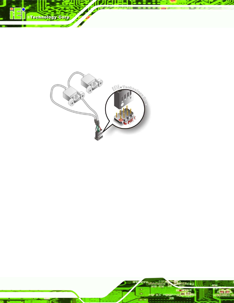
each cable connector with pin 1 on the NANO-945GSE USB connector.
Step 3:
Insert the cable connectors. Once the cable connectors are properly aligned
with the USB connectors on the NANO-945GSE, connect the cable connectors
to the on-board connectors. See
912H
Figure 5-19.
Figure 5-19: Dual USB Cable Connection
Step 4:
Attach the USB connectors to the chassis. The USB 2.0 connectors each of
two retention screw holes. To secure the connectors to the chassis please refer
to the installation instructions that came with the chassis.
Step 0:
5.7.9 Parallel Port Cable without Bracket
The optional parallel port (LPT) cable respectively connects the on-board LPT 26-pin box
header to an external LPT device (like a printer). The cable comprises a 26-pin female
header, to be connected to the on-board LPT box-header, on one side and on the other
side a standard external LPT connector. To connect the LPT cable, please follow the
steps below.
Step 1:
Locate the connector. The LPT connector location is shown in Chapter 4.
Step 2:
Align the connectors. Correctly align pin 1 on the cable connector with pin 1 on
the PCIE-9452 LPT box-header connector. See
913H
Figure 5-20.