3 ethernet and usb 3.0 connectors, And table 3-35: lan1, Pinouts – IEI Integration KINO-DQM871 User Manual
Page 67: Table 3-33: connector leds, Table 3-34: external usb 2.0 port pinouts, Table 3-35: lan1 pinouts
KINO-DQM871 Mini-ITX SBC
Page 51
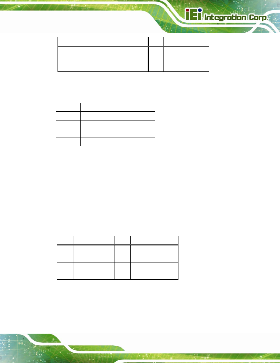
LED Description
LED Description
A on:
linked
blinking: data is being sent/received
B
off: 10 Mb/s
green: 100 Mb/s
orange: 1000 Mb/s
Table 3-33: Connector LEDs
The USB 2.0 connector can be connected to a USB device.
Pin Description
1 VBUS
2 D1-
3 D1+
4 GND
Table 3-34: External USB 2.0 Port Pinouts
3.3.3 Ethernet and USB 3.0 Connectors
CN Label:
LAN1_USB1
CN Type:
RJ-45 and USB 3.0 combo connector
CN Location:
CN Pinouts:
The LAN connector connects to a local network. It supports Intel® AMT 9.0.
PIN
DESCRIPTION
PIN
DESCRIPTION
1
MDIA0+
5
MDIA2-
2
MDIA0-
6
MDIA1-
3
MDIA1+
7
MDIA3+
4
MDIA2+
8
MDIA3-
Table 3-35: LAN1 Pinouts
See also other documents in the category IEI Integration Hardware:
- SPCIE-5100DX (180 pages)
- SPCIE-C2060 v1.01 (200 pages)
- SPCIE-C2060 v2.12 (212 pages)
- SPCIE-C2160 (204 pages)
- SPCIE-C2260-i2 (217 pages)
- ROCKY-3786 v4.0 (175 pages)
- ROCKY-3786 v4.10 (147 pages)
- PCIE-Q350 v1.00 (272 pages)
- PCIE-Q350 v1.12 (250 pages)
- PCIE-Q350 v1.20 (250 pages)
- PCIE-Q350 v1.30 (213 pages)
- PCIE-Q57A (159 pages)
- PCIE-G41A2 (151 pages)
- PCIE-Q670 v1.03 (206 pages)
- PCIE-Q670 v2.00 (205 pages)
- PCIE-H610 (181 pages)
- PCIE-Q870-i2 (217 pages)
- IOWA-LX-600 (159 pages)
- PCISA-945GSE v1.01 (207 pages)
- PCISA-945GSE v1.10 (190 pages)
- PCISA-9652 v1.00 (232 pages)
- PCISA-9652 v1.01 (232 pages)
- PCISA-PV-D4251_N4551_D5251 (145 pages)
- PICOe-945GSE (197 pages)
- PICOe-GM45A (198 pages)
- PICOe-PV-D4251_N4551_D5251 v1.00 (154 pages)
- PICOe-PV-D4251_N4551_D5251 v1.10 (154 pages)
- PICOe-PV-D4251_N4551_D5251 v1.11 (155 pages)
- PICOe-B650 (156 pages)
- PICOe-HM650 (174 pages)
- HYPER-KBN (139 pages)
- SPXE-14S (3 pages)
- SPXE-9S v1.00 (5 pages)
- SPXE-9S v1.1 (6 pages)
- SPE-9S v1.00 (4 pages)
- SPE-9S v1.1 (5 pages)
- SPE-6S (3 pages)
- SPE-4S (4 pages)
- PE-6SD3 (4 pages)
- PE-6SD2 v4.0 (4 pages)
- PE-6SD2 v2.10 (3 pages)
- PE-6SD (3 pages)
- PE-6S3 v1.0 (2 pages)
- PE-6S3 v4.0 (4 pages)
- PE-6S2 (4 pages)