5 example 4 - master ratio controller, Figure 3-4. master ratio controller – Micromod Micro-DCI: 53MC5000 Multi-Loop Process Controller FLEXIBLE CONTROL STRATEGIES User Manual
Page 84
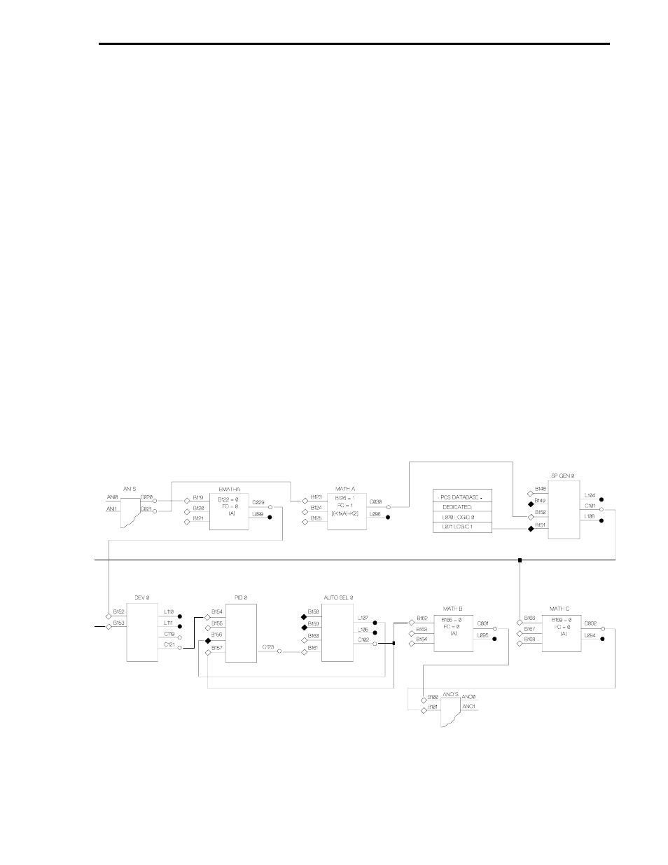
3.5 EXAMPLE 4 - MASTER RATIO CONTROLLER
As shown in Figure 3-4 below, this control strategy accepts two inputs: the Controlled Variable
(CV) at ANI0 and the Remote Setpoint (RSP) or Wild Variable at ANI1. The CV passes through
the Emath A module unaffected (FC=0) before being applied to the input of the Deviation 0 module.
The RSP is ratio augmented by the FC = 1 [(K1xA)+K2] of the Math A module before being applied
to Setpoint Generator 0. Setpoint Generator 0 is primed to pass the RSP because a logical 1 is al-
ways applied to input B151 from datapoint L071. The RSP output of the Setpoint Generator 0 mod-
ule is applied to the Deviation 0 module where it is compared to the CV. The RSP output of the
Setpoint Generator 0 module also passes through the Math C module (FC=0) to ANO1 as output
for a slave ratio controller.
At the Deviation 0 module, the difference between the CV and RSP is the error signal, which is
passed on to the Auto/Manual Select 0 module. Output from the Auto/Manual Select 0 module is
split two ways: as a required feedback path to the PID 0 module for reset action (TR) and to the
Math B module. The feedback path is active when Reset Action TR is not set to 0; it is gated back
into the PID 0 module when L107 is true (a logical 1 that indicates auto, and not manual operation).
The error signal from the Auto/Manual Select 0 module passes through the Math B module to
ANO0 as the PCS output to the process control instrument.
The Emath A, Math B, and Math C modules can have other FCs implemented for signal augment-
ing as required.
Figure 3-4. Master Ratio Controller
Section 3. FCS Wirelist Examples
EX5
3-19