3 example 2 - logic operated switch, Figure 3-2. logic operated switch, Table 3-2. logic operated switch - cci0 = 1 – Micromod Micro-DCI: 53MC5000 Multi-Loop Process Controller FLEXIBLE CONTROL STRATEGIES User Manual
Page 70
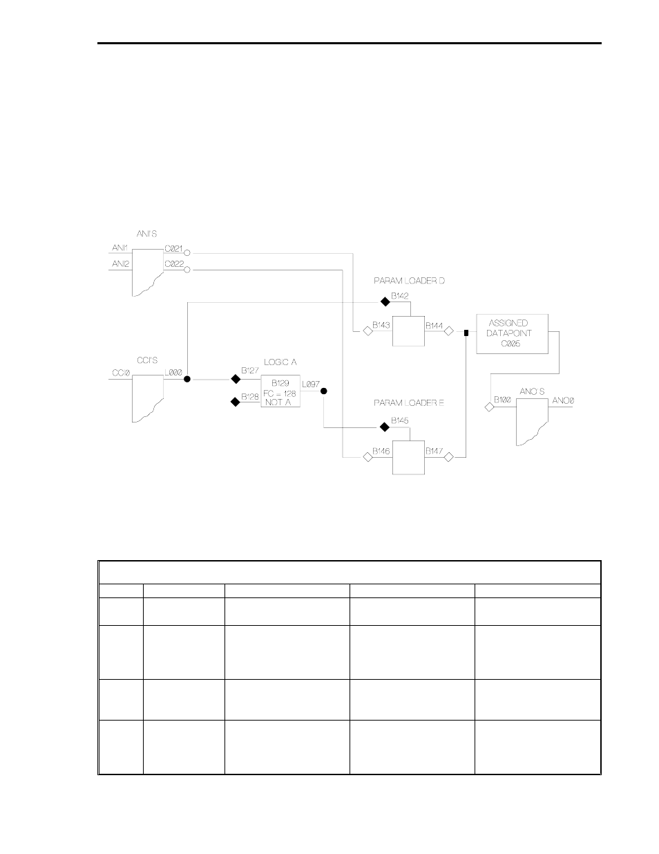
3.3 EXAMPLE 2 - LOGIC OPERATED SWITCH
Signal switching is built into the Setpoint Generator and Auto/Manual Selector modules, and condi-
tional signal switching can be affected using the Math modules. Figure 3-2 below illustrates an in-
dependent logic operated switch that uses two Parameter Loader modules and a Logic module.
Either ANI1 or ANI2 are selected as the output for ANO0 as determined by the state of CCI0 (if
CCI0 = 1, then ANI1 is the output; if CCI0 = 0, then ANI2 is the output). It is assumed the CCI0 out-
put is not inverted: 1 = closed contact and 0 = open contact. (It should be noted that if ANO1 is
used as the selected output, instead of ANO0, then this strategy can be executed concurrent with
the standard loop control.)
Figure 3-2. Logic Operated Switch
If CCI0 = 1, the following event sequence occurs as described in Table 3-2:
Table 3-2. Logic Operated Switch - CCI0 = 1
Step
Module
Input(s)
Output(s)
Comments
1
ANI
ANI1 (C021) and
ANI2 (C022).
2
Param D
B143 = C021 (ANI1)
and B142 = L000,
which is 1 because
CC!0 is closed.
B144 = ANI1.
3
Logic A
B127 = 1.
L097 = 0.
FC = 128 or A NOT;
therefore, a 1 in = a 0
out.
4
Param E
B146 = C022 (ANI2)
and B145 = L097,
which is 0 and inhibits
the output.
Section 3. FCS Wirelist Examples
EX2
3-5