36 control 3 – Micromod Micro-DCI: 53MC5000 Multi-Loop Process Controller FLEXIBLE CONTROL STRATEGIES User Manual
Page 58
2.7.36 CONTROL 3
The Control 3 (CON 3) module combines the operations of Deviation/Alarm Calculation (D/C) and
Proportional Integral Derivative (PID) modules. The D/C functionality of the CON 3 module calcu-
lates the deviation (DV) value from the setpoint (SP) and the process variable (PV). Before the cal-
culation is performed, the setpoint value is conditioned not to exceed the T1 rate of change limit. If
the calculated deviation falls within the Control Zone (CZ) value, the deviation is forced to 0.0. If
the DV value exceeds parameter values that were entered for alarm limits PL1 and PL2, and the
Alarm Deadband (ADB), then Process Alarms PA1 and PA2 are activated as determined by the
Control Alarm Mode (AIX) parameter selection. The DV output from the D/C functionality is routed
internally as the DV input to the PID functionality, which means it can not be accessed as a wirelist
datapoint as would be the case if both modules were separate. The PID functionality computes the
Control Output (CO) signal based on the DV input from the D/C, other input variables, and parame-
ter entries (see Section 2.7.15 or 2.7.26 for PID formulas).
When the Auto/Manual Switch 3 (AMS 3) module is in auto mode, the CON 3 CO output is forced
to equal the Auto Value (CO) out from the AMS 3 module.
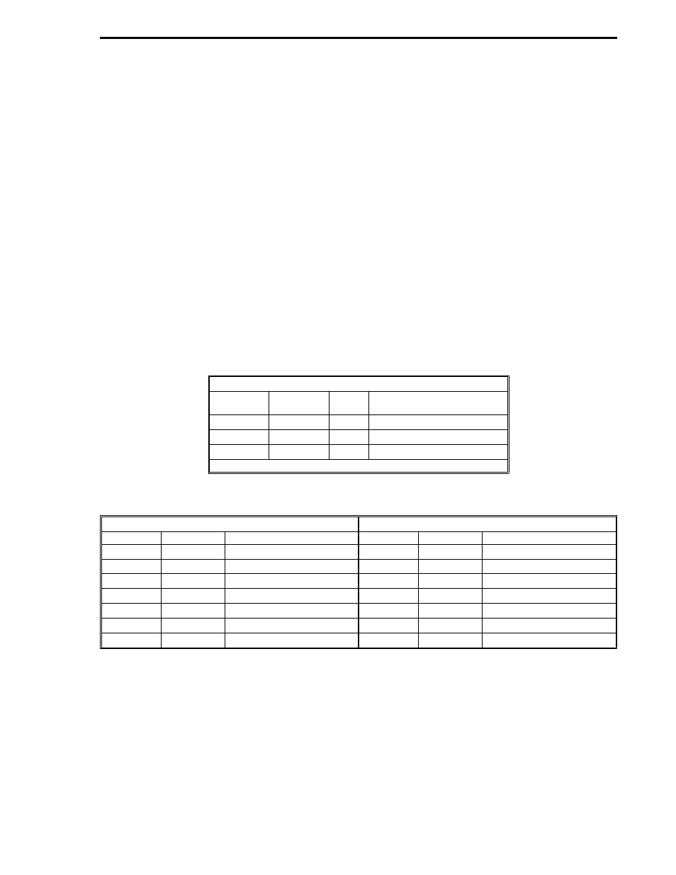
The tables that follow list the input variables and the parameters. An illustration of the Control 3
module follows the tables.
Inputs
WIRELIST
SYMBOL
DATA
TYPE
ASSIGNED VALUE
B230
PV3
C
B231
SP3
C
B232
FF3
C
Output Datapoints: C227, C229, C231, L182, L183
Parameters
Parameters
SYMBOL
DATAPOINT
ASSIGNED VALUE
SYMBOL
DATAPOINT
ASSIGNED VALUE
T1-3
C225
OL3
C218
CZ3
C222
IR3
C223
PL1-3
C211
PB3
C214
PL2-3
C212
TR3
C215
ADB3
C213
TD3
C216
AIX3
B350
MR3
C219
OH3
C217
RSW3
L178
Section 2. FCS Modules
CON-3
2-51