Micromod Micro-DCI: 53MC5000 Multi-Loop Process Controller FLEXIBLE CONTROL STRATEGIES User Manual
Page 20
2.7.4.3 COMPENSATED GAS FLOW (FC = 18 OR FC = 19)
Pressure and temperature compensated gas flow equations for both linear and square root flow ele-
ments are provided. These equations can be used to compute mass flow or
standard volume flow
of a gas. The equations handle both perfect and imperfect gases. Three inputs representing flow
[differential pressure] (A), absolute pressure (B) and absolute temperature (C) are converted to a
flow output signal based on a set of parameter constants (K1-K6).
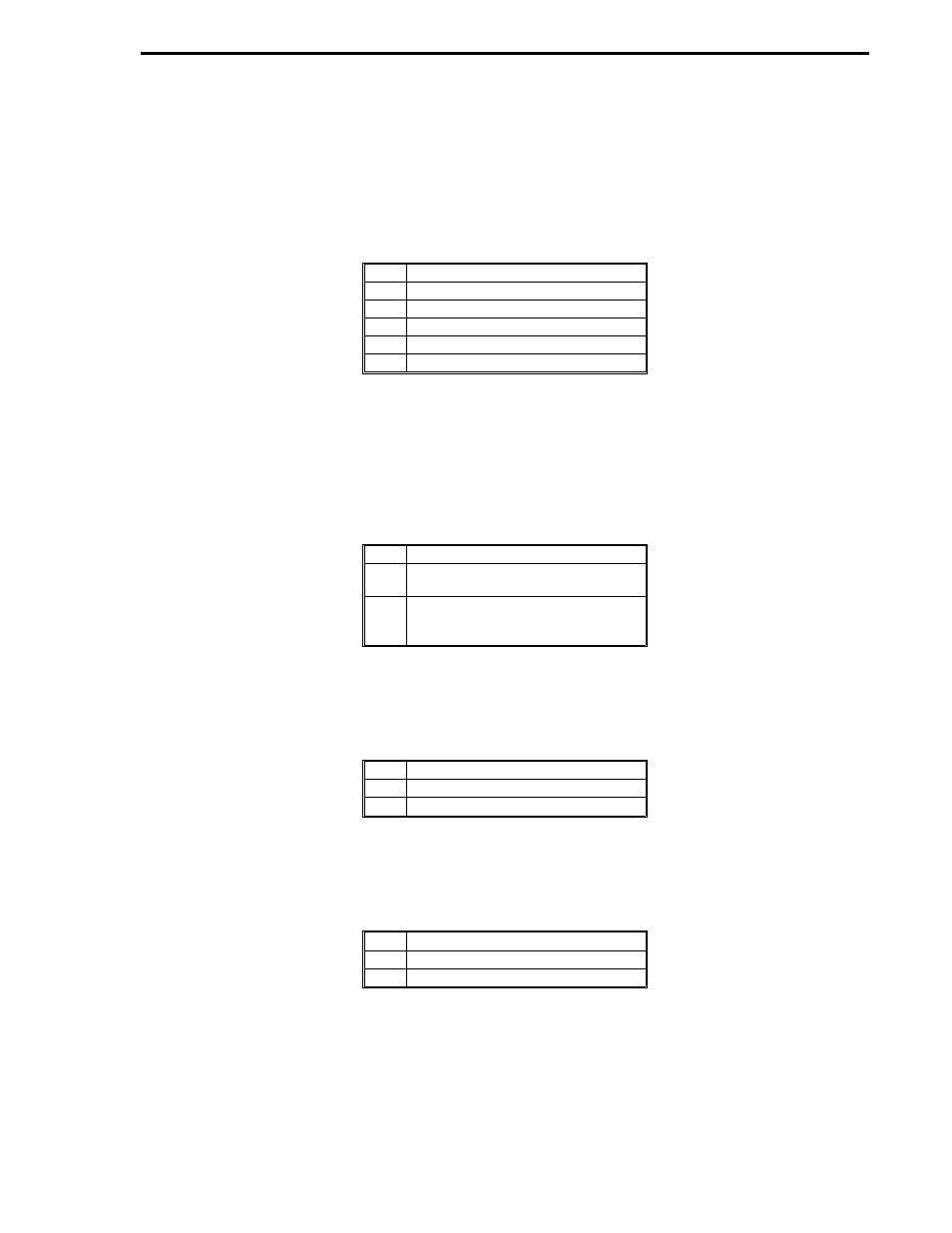
K1
Overall meter coefficient
K2
Slope of Y factor line (negative)
K3
Coefficient in density equation
K4
Pressure bias in density equation
K5
Temperature bias in density equation
K6
Density bias in density equation
How to evaluate constants K3, K4, K5 and K6 is covered in
Technical Information Bulletin 10E-10b
while constants K1 and K2 are covered by
Technical Information Bulletin 10B-9. Calculating den-
sity of natural gas for specific gravities, CO2 content and N2 content is examined in
A.G.A. report
number 3.
If gas behaves as a perfect gas in the zone of operation:
K4
Pressure bias in density equation = 0
K5
Temperature bias in density equation
= 460
°
R or 273
°
K
K6
Density bias in density equation =
molecular weight/Universal Gas
Constant, R
If acoustic ratio is very low, Y = 1.0, then K2 = 0.
Linear Flow Element Compensation:
A
Acfm actual volumetric flow
B
Pabs absolute pressure
C
T temperature Rankin or Kelvin
OUT = K1
×
A
×
Dens
Dens = K3
×
(( B - K4 )/( C + K5 )) + K6
Square Root Flow Element Compensation:
A
Pdel measured differential pressure
B
Pabs absolute pressure
C
T temperature Rankin or Kelvin
OUT = K1
×
Y
×
( A
∗
Dens )
1/2
Y = 1 - K2
×
( A / B)
Dens = K3
×
(( B - K4 )/( C + K5 )) + K6
Section 2. FCS Modules
EMATH-A
2-13