0 fcs modules, 1 overview, 2 fcs module description – Micromod Micro-DCI: 53MC5000 Multi-Loop Process Controller FLEXIBLE CONTROL STRATEGIES User Manual
Page 8
2.0 FCS MODULES
2.1 OVERVIEW
The Flexible Control Strategy (FCS) modules are the building blocks of the controller functionality.
The modules are presented symbolically with inputs and outputs to eliminate the necessity of learn-
ing a programming language; however, each symbol actually represents coded instructions that
are executed by the Process Control Station (PCS). The order in which the modules are con-
nected determines the instruction flow executed by the PCS. Because each module is a coded in-
struction set, connecting the modules does not require any physical alteration to the PCS hardware
but is accomplished by configuring an assigned list of memory datapoints. The assigned list is
called a worksheet and after the worksheet is completed, the connected datapoint values are en-
tered into the PCS memory. Connecting the datapoints is sometimes called
wiring, a term that is
still carried-over today from the earliest electronic processors when the hardware functions of a de-
vice were selectively connected one-to-another with jumper wires.
2.2 FCS MODULE DESCRIPTION
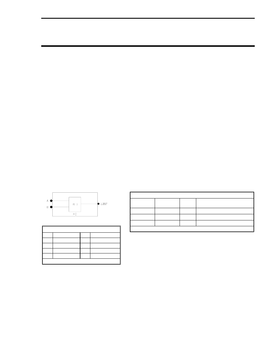
As shown in the figure below, each module has an associated set of input signal designators
shown as diamonds, output signal points shown as a circle(s), and an operational function code
(FC) where applicable. The wirelist datapoints assigned to the input diamonds, output circle(s),
and function code (if applicable) are all listed in the
Inputs table that is provided with each module
description. A separate
Functions table, which describes each function code, is also provided for
those modules that perform mathematical or logical functions.
Logic Module A
The
Inputs table above indicates the wirelist datapoint assignments for inputs A and B are B127
and B128 respectively. The wirelist datapoint assignment for the FC is B129 and the output value
that is accessible to other modules in the FCS sequence is L097.
FCS signals are of two types: logical L-values (0 or 1) and numeric C-values. Logical L-values are
shown as solid diamonds for input signals and solid circles for output signals. Numeric C-values
are shown as open diamonds for input signals and open circles for output signals. Logical and nu-
meric values can not be cross-wired from one module to another, that is, the logical output of one
Logic Functions
FC
OUTPUT
FC
OUTPUT
0
A
4
A OR NOT B
1
A OR B
5
A AND NOT B
2
A AND B
6
J-K LATCH
3
A XOR B
7
D LATCH
Invert output if FC = FC + 128
Inputs
WIRELIST
SYMBOL
DATA
TYPE
ASSIGNED VALUE
B127
A
L
B128
B
L
B129
FC
N/A
Output Datapoint: L097
Section 2. FCS Modules
3-1TXT
2–1