Outputs, Outputs -19, Speed command out – CONTREX M-Traverse User Manual
Page 34: Drive enable (j1 pin 13)
2 - 19
OUTPUTS
NOTE: The installation of this motor control must conform to area and local electrical
codes. See
The National Electrical Code
(NEC,) Article 430 published by the
National Fire Protection Association, or
The Canadian Electrical Code
(CEC).
Use local codes as applicable.
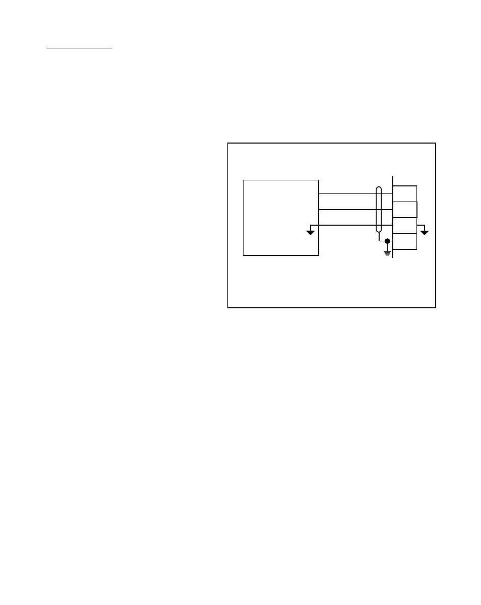
Speed Command Out
(J1 pins 8, 9,10,11)
Speed Command Out is an isolated
analog output signal that is sent to
the motor drive to control the speed
of the motor. Wire the Speed
Command Out (J1 pin 9) into the
Speed Signal Input of the drive. If
the motor drive has a potentiometer
speed control, remove the
potentiometer connections, then wire
the Speed Command Output to the
potentiometer wiper input and wire
the Voltage Reference and Isolated
Common to the other two
potentiometer input connections. The
M–Traverse's isolated common
should always be connected to the
drive common.
*
MOTOR DRIVE
8
9
10
11
J1
SIGNAL INPUT
Speed Command Out
Isolated Common
DRIVE COMMON
Voltage Reference
Shield
±
V (15V Max)
Figure 2-24 Speed Command Out
Drive Enable (J1 pin 13)
The Drive Enable output is activated (driven low) when the M–Traverse is signaling a
speed command to the motor drive. The Drive Enable output is driven high (relay
deactivated) after Power Up and during F–Stop. Refer to Figure 2-25.
NOTE: This is an open-collector relay driver. For specification details, see
Refer-
ences: Appendix A
,
M–Traverse Specifications
. Use an external DC power
supply to power the relays. Free-wheeling diodes are incorporated internally
in the M–Traverse and do not need to be added externally.