Electrical connection with cable gland, Designation of the screw-type terminals, Connection of the screw-type terminals – Burkert Type 8791 User Manual
Page 52
52
Electrical connection
13.3. electrical connection with cable gland
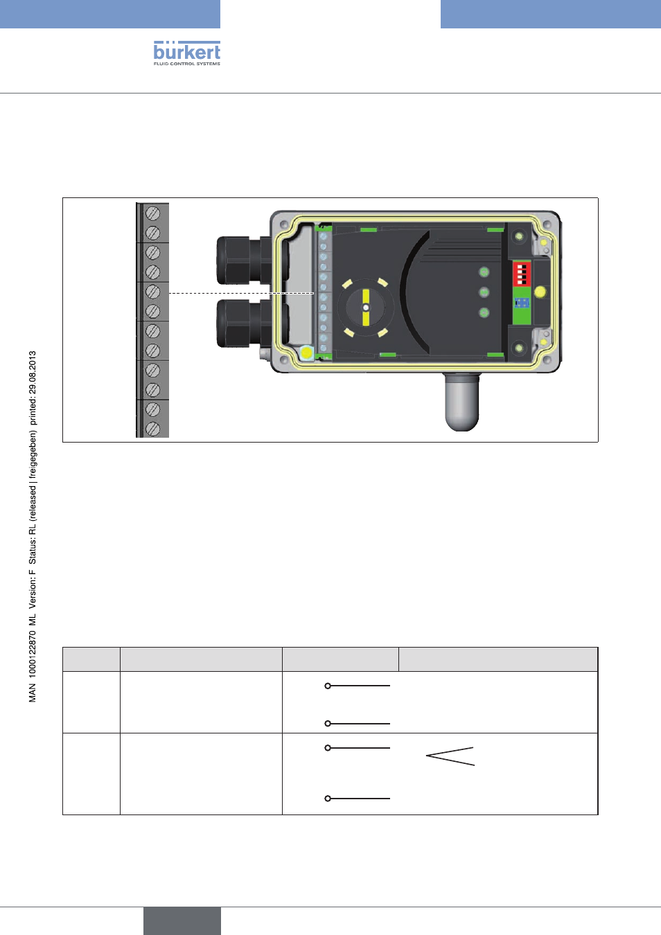
13.3.1. Designation of the screw-type terminals
11 +
12 –
81
82
31 +
32 –
A
B
+
–
+24 V
GND
remote
sensor
Figure 26:
Designation of the screw-type terminals
13.3.2. connection of the screw-type terminals
→
Unscrew the 4 screws on the housing cover and remove the cover.
The screw-type terminals are now accessible.
→
Connect terminals according to the configuration.
13.3.3. Terminal assignment for input signals from the control
centre (e.g. plc)
terminal
configuration
On the device side
external circuit / signal level
11 +
Set-point value +
11 +
+ (0/4 – 20 mA)
not galvanically isolated
12 –
Set-point value GND
12 –
GND set-point value
81 +
Binary input +
81 +
+
0 – 5 V (log. 0)
10 – 30 V (log. 1)
82 –
Binary input –
82 –
GND (identical with the GND supply
voltage)
Table 26:
Terminal assignment; input signals of the control centre
english
Type 8791