Fluidic connection of the top control continuous – Burkert Type 8630 User Manual
Page 45
8630 - 43
I
NSTALLATION
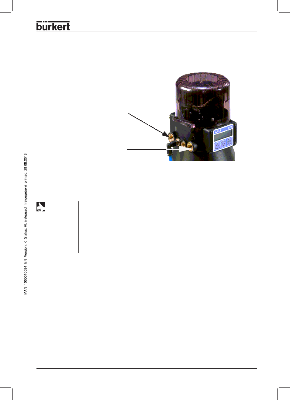
Fluidic connection of the TOP Control Continuous
➔ Apply the supply pressure to
connection“1" (3..7 bar, instrument
air, free from oil, water and dust)
➔ Attach the exhaust line or silencer
to connection „3“
NOTE
Maintain the applied supply pressure, without fail
, at least 0.5 - 1 bar over that required
to bring the pneumatic actuator into the end position. This assures that the control
behaviour in the upper region of the stroke will not be significantly affected negatively if
the pressure difference is too small.
Keep variations in the supply pressure as low as possible during operation (max. ± 10
%). With larger variations, the controller parameters calibrated with the AUTOTUNE
function will not be optimal.
Remove the protective caps from the valve and the TOP Control Continuous.
- Type 0125 (15 pages)
- Type 0121 (4 pages)
- Type 0330 (2 pages)
- Type 0331 (4 pages)
- Type 6012 (4 pages)
- Type 0127 (18 pages)
- Type 0131 (5 pages)
- Type 0141 (5 pages)
- Type 0142 (12 pages)
- Type 0145 (3 pages)
- Type 0174 (5 pages)
- Type 0212 (2 pages)
- Type 0211 (5 pages)
- Type 0212-B (18 pages)
- Type 0250 (64 pages)
- Type 0253 (2 pages)
- Type 0255 (15 pages)
- Type 0355 (2 pages)
- Type 0255 (2 pages)
- Type 8006 (34 pages)
- Type 8640 (2 pages)
- Type 8640 (55 pages)
- Type 8640 (119 pages)
- Type 0256 (15 pages)
- Type 0256 (2 pages)
- Type 0258 (72 pages)
- Type 0262 (5 pages)
- Type 0273 (6 pages)
- Type 0280 (5 pages)
- Type 0280 (2 pages)
- Type 0280 (12 pages)
- Type 0281 (2 pages)
- Type 0282 (2 pages)
- Type 0283 (2 pages)
- Type 0286 (4 pages)
- Type 0287 (15 pages)
- Type 0290 (2 pages)
- Type 0290 (14 pages)
- Type 0293 (18 pages)
- Type 0300 (6 pages)
- Type 0301 (6 pages)
- Type 0311 (2 pages)
- Type 0312 (6 pages)
- Type 6519 (3 pages)
- Type 6519 (4 pages)