Atec Fluke-OF-500 User Manual
Page 29
Basic Features
19
A
Connector for the ac adapter. The LED turns on when the
adapter is connected to ac power.
B
USB port for uploading test reports to a PC and
downloading software updates from a PC to the tester.
See the LinkWare documentation for details on using the
USB port.
C
Six-pin mini DIN connector for an optional external PS2
keyboard.
D
Eight-pin mini DIN connector for the optional
FiberInspector video probe.
E
Fan vents.
F
RS-232C serial port for uploading test reports to a PC and
downloading software updates from a PC to the tester.
See the LinkWare documentation for details on using the
serial port.
G
Slot for the removable memory card. The LED lights when
the tester is writing to or reading from the memory card.
H
Multimode (MM) or singlemode (SM) label for the module.
I
OFTM-57xx: Connector for the visual fault locator.
J
OTDR connector adapter (SC is standard). The LED
lights when the laser is active.
K
OFTM-5612B/5732: Loss/length output port (SC).
Transmits optical signals for loss/length tests.
L
OFTM-5731/5732/5611B/5612B: Loss/length input
port with interchangeable connector adapter (SC is
standard). Receives optical signals for power
measurements and loss/length tests.
W*
Warning
Never look directly into optical connectors.
Some sources produce invisible radiation that
can permanently damage your eyes.
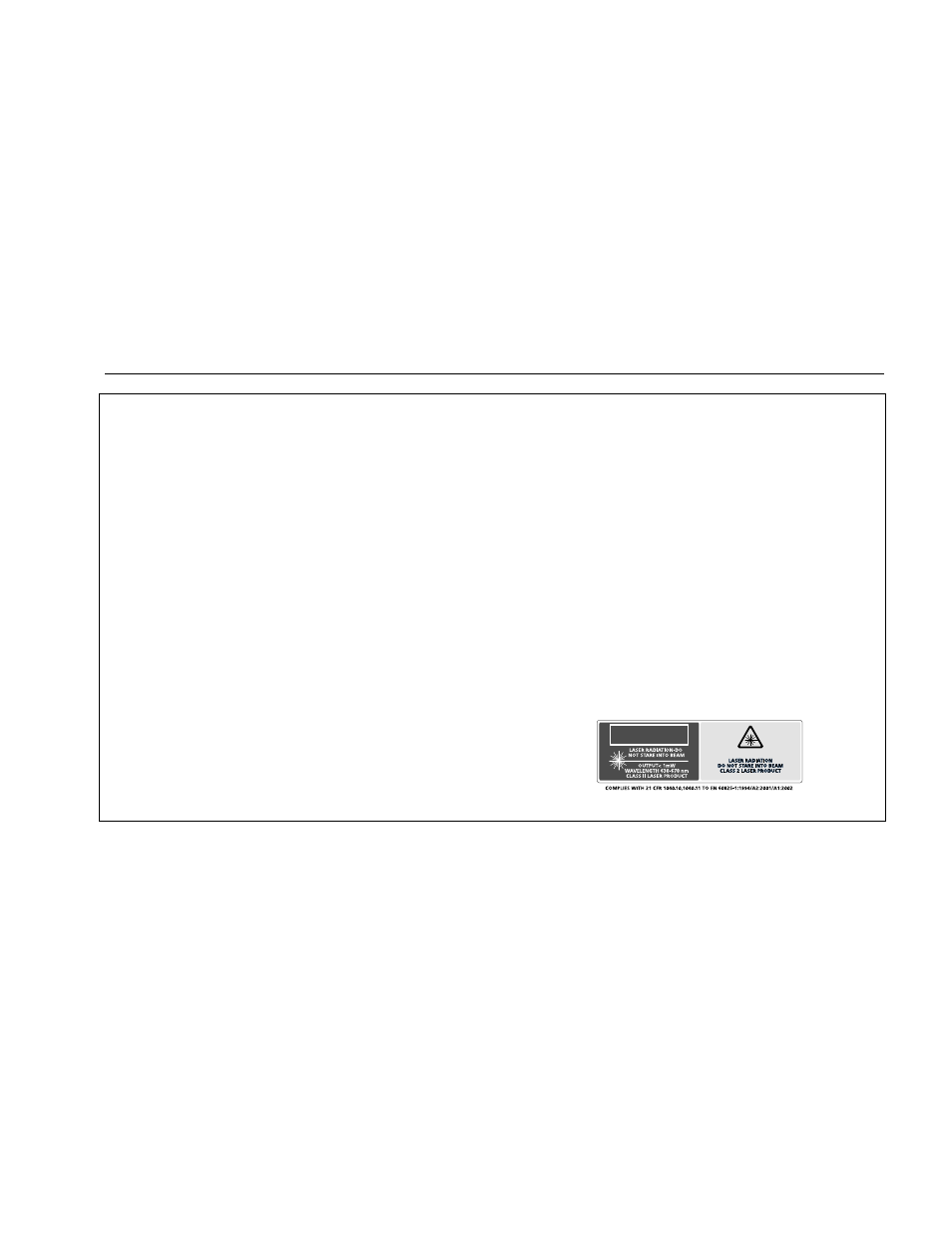
M
Laser safety label (shown below).
CAUTION
ajt72f.eps
Figure 4. Side and Top Panel Features (cont.)