Atec Agilent-E8364B User Manual
Page 11
7
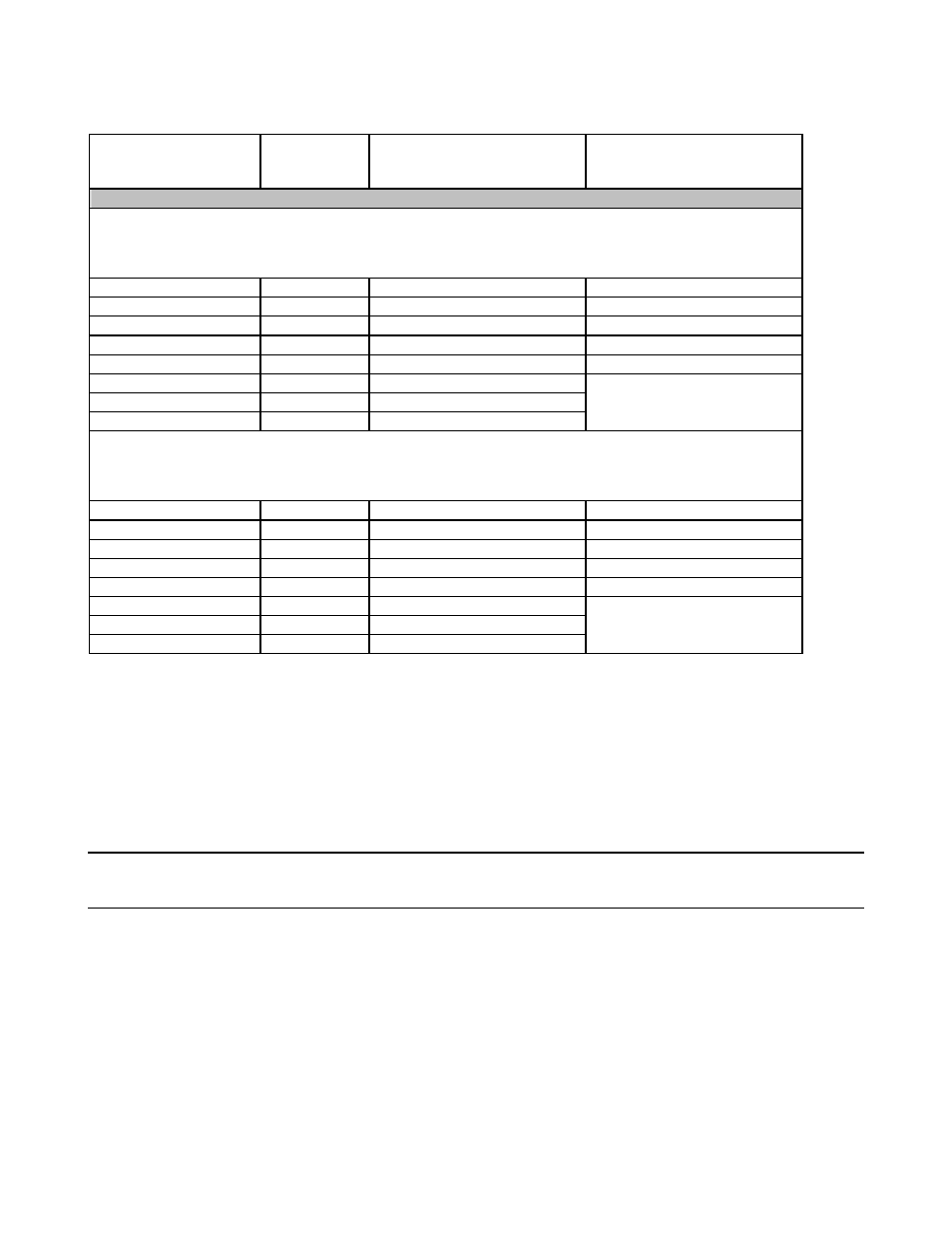
Table 2. Receiver Dynamic Range
a
Description
Specification
(dB) at Test
Port
b
Typical (dB) at Direct
Receiver Access Input
c
Dynamic Range (in a 10 Hz BW)
Standard Configuration and Standard Power Range (E836xB/C - Standard)
OR
Standard Configuration and Extended Power Range & Bias Tees (E836xB/C - Option UNL)
10 MHz to 45 MHz
d
82 (typical)
NA
--
45 MHz to 500 MHz
e
94
NA
--
500 MHz to 2 GHz
119
NA
--
2 GHz to 10 GHz
122
NA
--
10 GHz to 20 GHz
125
NA
--
20 GHz to 30 GHz
114
NA
30 GHz to 40 GHz
111
NA
40 GHz to 50 GHz
111
NA
Option 016 degrades
performance by 2 dB.
Configurable Test Set and Standard Power Range (E836xB/C - Option 014)
OR
Configurable Test Set and Extended Power Range & Bias Tees (E836xB/C - Option 014/UNL)
10 MHz to 45 MHz
d
82 (typical)
132
--
45 MHz to 500 MHz
e
94
132
--
500 MHz to 2 GHz
119
138
--
2 GHz to 10 GHz
122
137
--
10 GHz to 20 GHz
124
139
--
20 GHz to 30 GHz
113
125
30 GHz to 40 GHz
110
122
40 GHz to 50 GHz
109
120
Option 016 degrades
performance by 2 dB.
a
The receiver dynamic range is calculated as the difference between the noise floor and the receiver maximum output power. The effective
dynamic range must take measurement uncertainties and interfering signals into account.
b
The test port receiver dynamic range is calculated as the difference between the test port noise floor and the receiver maximum input
level. The effective dynamic range must take measurement uncertainties and interfering signals into account.
c
The direct receiver access input receiver dynamic range is calculated as the difference between the direct receiver access input noise floor
and the receiver maximum input level. The effective dynamic range must take measurement uncertainties and interfering signals into
account. This set-up should only be used when the receiver input will never exceed its compression or damage level. When the analyzer is
in segment sweep mode, the analyzer can have predefined frequency segments which will output a higher power level when the extended
dynamic range is required (i.e. devices with high insertion loss), and reduced power when compression or receiver damage may occur (i.e.
devices with low insertion loss). The extended range is only available in one-path transmission measurements.
d
Typical performance.
e
May be degraded by 10 dB at particular frequencies (multiples of 5 MHz) below 500 MHz due to spurious receiver residuals. Methods are
available to regain the full dynamic range.
Note: This E836xB/C document provides technical specifications for the following calibration kits only: 85056A,
85056D, 85056K, 85052B, 85052C, 85052D, 85050B, 85050C, 85050D, 85054B, 85054D, K11644A, P11644A,
R11644A, and the X11644A.