Probing configurations, Recommended probe configurations – Atec Agilent-346a User Manual
Page 67
67
Agilent 16517A/16518A 1 GHz State / 4 GHz Timing
"ADAPTER CABLE"
BNC-SMB
16517-61604
"CALIBRATION POD"
16517-63201
These parts included in the
16517-68701 MASTER KIT only
NOTE: Examples of convenient connection which
may result in degraded performance
SIG.
SIG.
"GND CONNECTOR"
16515-27601
Probing Configurations
"SMT KIT"
16517-82104
Qty. 4 Black Incl.
Qty. 4 Red Incl.
SIG.
"PIN-PROBE KIT"
16517-82107
Qty. 4 Incl.
"GND LEAD KIT"
16517-82106
Qty. 20 incl.
SIG.
SIG.
"SMD IC CLIP KIT"
16517-82109
Qty. 20 incl.
"GND EXTENDER KIT"
16517-82105
Qty. 20 incl.
SIG.
"PROBE LEAD"
16517-61602
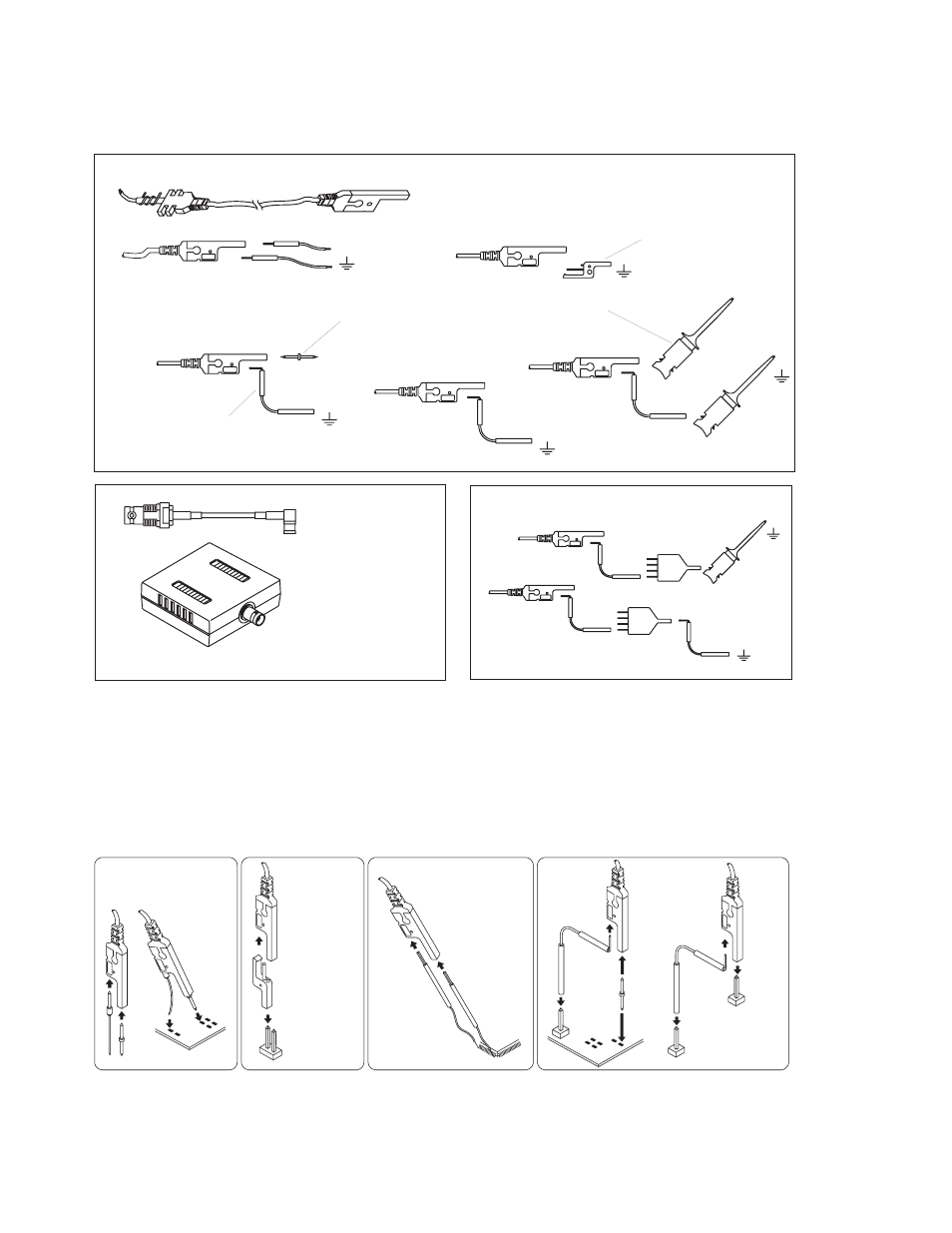
Figure 12.5. Agilent Technologies 16517-68701 master accessory kit and 16518-68701 expansion accessory kit
Pin and Socket Ground Lead
0.635mm (0.025")
square pin or
0.66-0.84mm
diameter pin
Flexible Direct Ground Pin
Ground Extender
SMT Tack-on Signal/Ground
Recommended Probe Configurations
For the best performance, use the following configurations. The configurations are listed in the recommended order.
Signal
Make contact with
the flexible ground
first, then flex it to
place the signal
pin.
Ground
Signal
Ground
Signal
Signal
Red
Ground
Black
Signal
Ground
0.635mm (0.025")
square pin or
0.66-0.84mm
diameter pin
Ground
Figure 12.6. Probing configurations that give the best signal fidelity