Atec Agilent-346a User Manual
Page 51
51
Designing and Probing with Target Connections
Agilent Logic Analyzers with 90-pin Pod Connectors
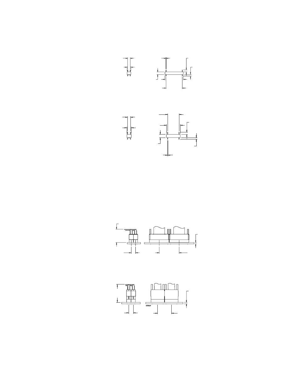
Retention Module Dimensions
The soft touch probes are
attached to the PC board using a
retention module which ensures
pin-to-pad alignment and holds
the probe in place. A board
thickness of up to 2.54 mm
(0.100 in.) is recommended.
Insert the retention module into
the board, noting the keying pin,
and solder the four alignment
pins to the backside of the board.
Probe and Retention Module
Dimensions
The following dimensions show
the soft touch probe attached
to the retention module. The
retention module is mounted on
the PC board.
Figure 8.11. Retention module dimensions
Figure 8.12. Probe and retention module dimensions
4.83 mm
_______
0.190 in.
6.99 mm
_______
0.275 in.
34.04 mm
________
1.340 in.
29.97 mm
________
1.180 in.
0.64 mm
_______
0.025 in.
4.98 mm
_______
0.196 in.
3.58 mm
_______
0.141 in.
2.72 mm
_______
0.107 in.
4.83 mm
_______
0.190 in.
6.99 mm
_______
0.275 in.
0.64 mm
________
0.025 in.
17.98 mm
_______
0.708 in.
4.98 mm
_______
0.196 in.
22.05 mm
_______
0.868 in.
3.58 mm
_______
0.141 in.
2.72 mm
_______
0.107 in.
2.54 mm
_______
0.100 in.
35.05 mm
________
1.380 in.
Minimum
recommended
8.13 mm
_______
0.320 in.
Minimum
recommended
25.35 mm
________
0.998 in.
17-channel retention module dimensions
34-channel retention module dimensions
2.54 mm
_______
0.100 in.
23.06 mm
________
0.908 in.
Minimum
recommended
8.13 mm
_______
0.320 in.
Minimum
recommended
29.61 mm
________
1.166 in.
17-channel probe and retention module dimensions
34-channel probe and retention module dimensions