Atec Agilent-346a User Manual
Page 53
53
Designing and Probing with Target Connections
Agilent Logic Analyzers with 90-pin Pod Connectors
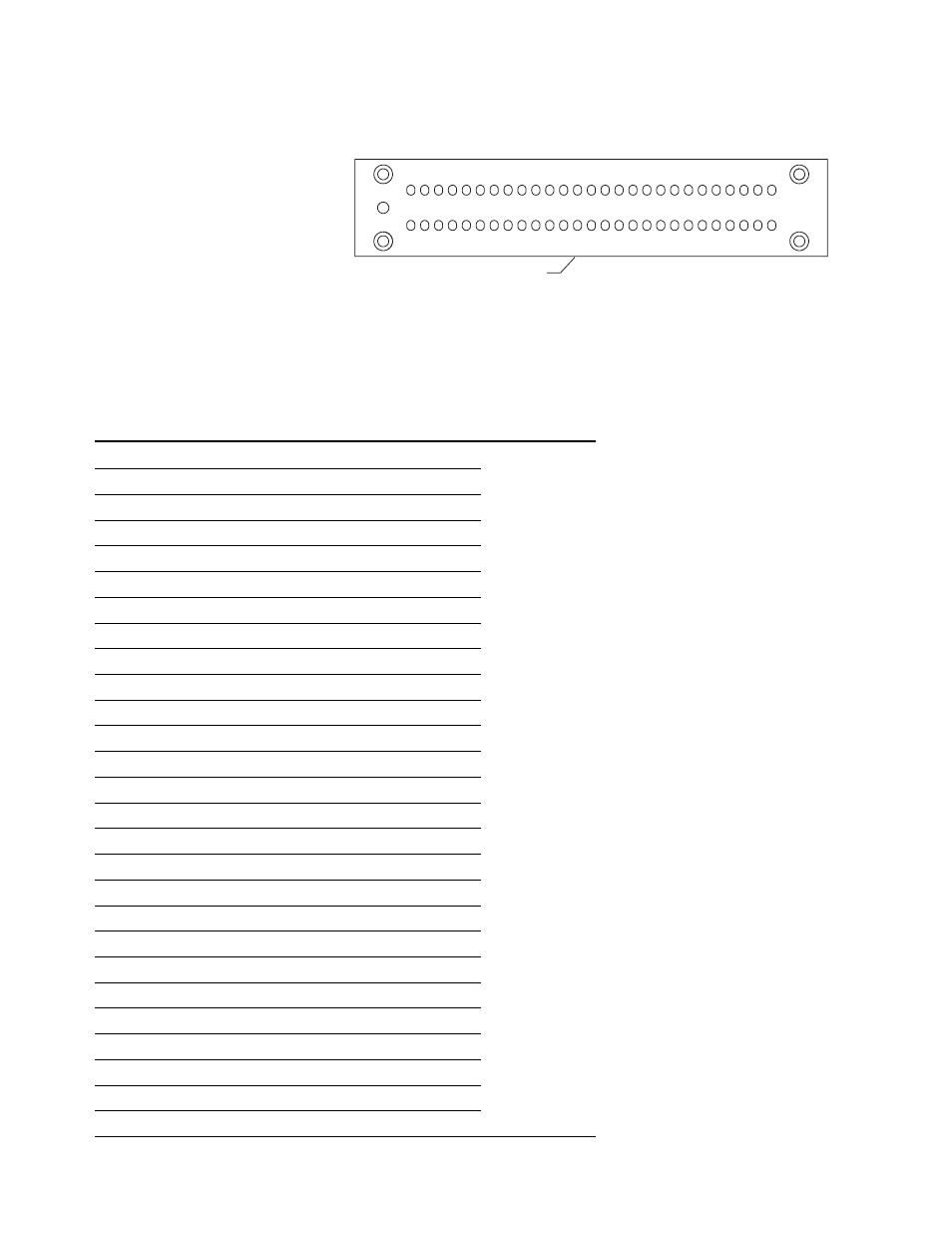
Pinout for the E5387A Differential
Soft Touch Probe
The following graphic and table
show the E5387A differential soft
touch probe pad numbers and
logic analyzer pod inputs.
Footprint keep out boundary
D0 D1 G D2 D3 G D4 D5 G D6 D7 G CLK G D8 D9 G D10 D11 G D12 D13 G D14 D15 G NC
nD0 nD1 G nD2 nD3 G nD4 nD5 G nD6 nD7 G nCLK G nD8 nD9 G nD10nD11 G nD12nD13 G nD14nD15 G NC
B1
A1
B27
A27
Figure 8.14. Pinout
E5387A Differential Probe
Negative Signals
Positive Signals
Logic Analyzer
Signal Name Pad #
Signal Name Pad #
Channel
Pod
D0 (–)
A1
D0 (+)
B1
➞
0
Whichever pod
D1 (–)
A2
D1 (+)
B2
➞
1
is plugged into
Ground
A3
Ground
B3
the E5387A probe
D2 (–)
A4
D2 (+)
B4
➞
2
D3 (–)
A5
D3 (+)
B5
➞
3
Ground
A6
Ground
B6
D4 (–)
A7
D4 (+)
B7
➞
4
D5 (–)
A8
D5 (+)
B8
➞
5
Ground
A9
Ground
B9
D6 (–)
A10
D6 (+)
B10
➞
6
D7 (–)
A11
D7 (+)
B11
➞
7
Ground
A12
Ground
B12
Clock (–)
A13
Clock (+)
B13
➞
Clock
Ground
A14
Ground
B14
D8 (–)
A15
D8 (+)
B15
➞
8
D9 (–)
A16
D9 (+)
B16
➞
9
Ground
A17
Ground
B17
D10 (–)
A18
D10 (+)
B18
➞
10
D11 (–)
A19
D11 (+)
B19
➞
11
Ground
A20
Ground
B20
D12 (–)
A21
D12 (+)
B21
➞
12
D13 (–)
A22
D13 (+)
B22
➞
13
Ground
A23
Ground
B23
D14 (–)
A24
D14 (+)
B24
➞
14
D15 (–)
A25
D15 (+)
B25
➞
15
Ground
A26
Ground
B26
N/C
A27
N/C
B27