Atec Agilent-346a User Manual
Page 40
40
Designing and Probing with Target Connections
For All Agilent Logic Analyzers with 40-pin Pod Connectors
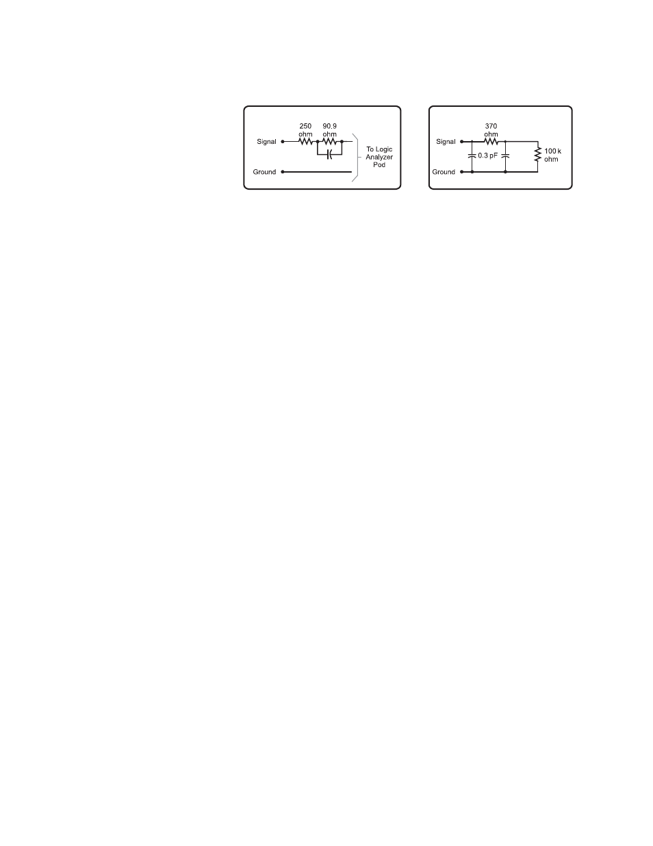
Notes on Using Discrete Components
Discrete components can be used
to design the isolation network.
Agilent Technologies recommends
the circuit shown in Figure 7.9.
To achieve the equivalent load
shown in the figure, trace lengths
should be minimized by locating
the RC network very near the
measured node. Actual load will
be the stub length load added to
the equivalent load in the figure.
Trace length from the suggested
on-board RC network to the
target connector must be 3 to
4 inches or less. This transmis-
sion line should be designed for
an impedance in the range of 80
to 100 ohms (closer to 100 ohms
is better).
Figure7.9. Equivalent load for on-target discrete components.
Also applies to SMT (5062-7396) RC networks.
k
8.2 pF
7.4 pF
Equivalent Load
Suggested On Board Isolation Network
Includes on board isolation network and
logic analyzer
- Anritsu-PIM-MW82119A (2 pages)
- Boonton-PIM31 (6 pages)
- AWT-PIM-S1L-Tetra Series (2 pages)
- AWT-PIM-S1P Series (2 pages)
- AWT-PIM-S1L Series (2 pages)
- AWT-PIM-Expandable Series (2 pages)
- AWT-PIM-Single Series (2 pages)
- CCI-PimPro (4 pages)
- JDSU-FST-2310 (10 pages)
- JDSU-T-Berd-6000 (8 pages)
- Agilent-N9912A (2 pages)
- Agilent-E5515C (4 pages)
- Agilent-E4406A (20 pages)
- Agilent-N4010A (16 pages)
- Anritsu-S412E (19 pages)
- Anritsu-S810D-S820D (2 pages)
- Anritsu-S820E (16 pages)
- Anritsu-MT8221B (24 pages)
- Anritsu-MT8221B (28 pages)
- Anritsu-S412D (16 pages)
- Anritsu-MT8222A (8 pages)
- Anritsu-MT8220T (28 pages)
- Anritsu-MT8212E-MT8213E (32 pages)
- Anritsu-S332D-31D (12 pages)
- Anritsu-MT8212A (2 pages)
- Bird-SA Series (2 pages)
- Anritsu-S331E-S332E-S361E-S362E (16 pages)
- Anritsu-S331L (12 pages)
- Advantest-Q8163 (1 page)
- Agilent-83557A-83558A (4 pages)
- Agilent-8169A (6 pages)
- Agilent-11896A (5 pages)
- Agilent-81689A_B-81649A (6 pages)
- Agilent-8163A-81634A (8 pages)
- Agilent-81624B (11 pages)
- Agilent-81618A (112 pages)
- Agilent-8703A (16 pages)
- Agilent-8156A (8 pages)
- Advanced-Fiber-Solutions-OLK51 Series (5 pages)
- Anritsu_MS9720A (12 pages)
- Anritsu-ML9001A (4 pages)
- Corning-Optivisor400 (6 pages)
- Anritsu_CMA5000a (4 pages)
- Agilent-E6008B (12 pages)
- AFL-Noyes-FLX3 (6 pages)