Atec Agilent-346a User Manual
Page 32
32
Designing and Probing with Target Connections
For All Agilent Logic Analyzers with 40-pin Pod Connectors
Options for On-Board Terminations
for the E5351A
There are two options for
isolating the E5351A on the
target PC board:
• Use the surface mount isola-
tion network, Agilent part
number 5062-7396. Refer
to Figure 5.26 for schematic
and pinout.
• Use discrete components.
Refer to Figure 5.25 for recom-
mended components and
equivalent load.
If you are operating at state
speeds above 200 MHz, you
should use discrete components
for best results. Due to the added
electrical length of the E5351A
probe cable, the divider compen-
sating capacitors in the SIP, and
surface-mount isolation networks
are not optimum for the E5351A,
but they are usable up to 200 MHz
clock rates.
Notes on Using the 5062-7396
SMT Part
Agilent currently recommends a
two-step process in soldering the
SMT part to the board. The first
pass places solder paste on those
pads with vias. Application of
heat allows the via to fill with
solder. (If only one solder step is
used, the solder wicks away from
the part into the via and a solid
connection will not be made with
the part.) The next pass places
solder paste on all of the pads.
As shown in Figure 5.26, the
5062-7396 SMT isolation network
supports six logic analysis
channels. The size of the part
allows you to repeat the pattern in
Figure 5.26 to accommodate mul-
tiple parts stacked end-to-end for
the number of channels needed in
your application. Three of these
SMTs are required for each probe
k
10 pF
9 pF
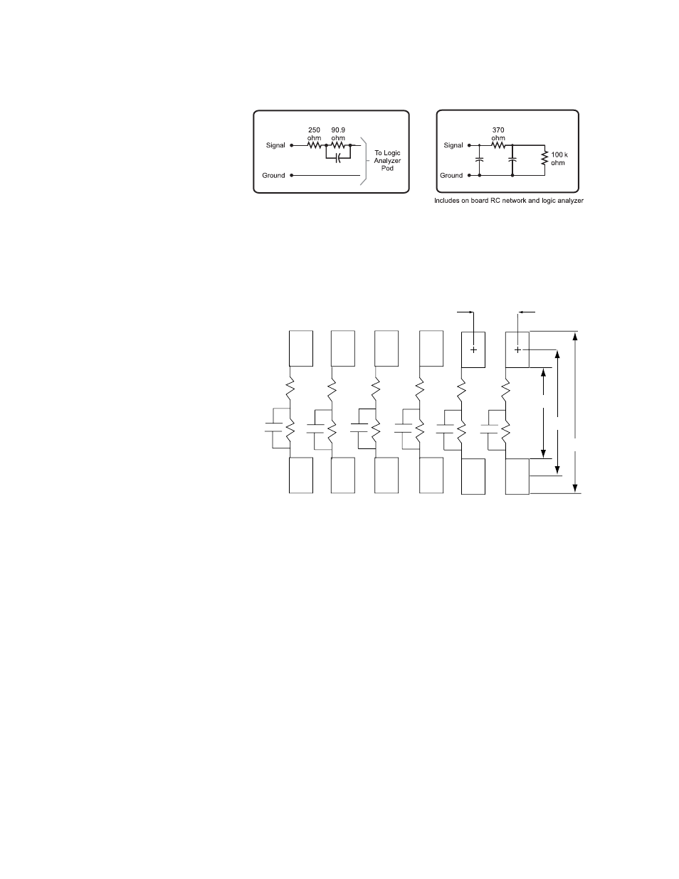
Suggested On Board Isolation Network
Equivalent Load
Note 1
Figure 5.25. Suggested on-board isolation network and equivalent load when using
discrete components to terminate the E5351A
Note 1: The effective input capacitance for on-board isolation networks is purely a function of geometry -
0.3 pF is about as low as can be achieved.
Note 2: The equivalent load is the same when using the surface-mount isolation network, 5062-7396.
Logic Analyzer Pod
Pad Dimension = 0.030” x 0.040”
7
5
8
9
10
3
11
2
1
12
0.050”
0.080”
0.120”
0.160”
R1
C1
R2
R3
R4
R5
R6
R7
C2
R8
C3
R9
C4
R10
C5
R11
C6
R12
Notes:
4
6
cable. The process for using the
ceramic hybrid isolation network
is similar to the process for an
LCC package. Due to the small
part size, thermal expansion
mismatch during solder reflow
should not be a problem.
Capacitance also remains stable
with temperature changes.
1. Resistances:
R1 through R6: 250
Ω
R7 through R12: 90.9 k
Ω
2. Capacitance 8.2 pF
Figure 5.26. Recommended PC board pattern for 5062-7396 surface mount
isolation network