Atec Agilent-346a User Manual
Page 38
38
Designing and Probing with Target Connections
For All Agilent Logic Analyzers with 40-pin Pod Connectors
Direct Connection through
40-Pin Connectors
The probe cable also can be
plugged directly into the various
40-pin connectors shown in
Table 7, but proper isolation
networks must be installed
directly onto the target system
board (see Figure 7.6 for the
40-pin connector pinout).
Agilent Technologies offers a
12-pin SMT (Agilent part number
5062-7396), which provides six
isolation networks, as shown in
Figure 7.7. Three of these SMTs
are required for each probe cable.
Discrete components can also be
used for the proper isolation
network. See Figure 7.9 for an
equivalent load diagram for the
isolation networks.
Note that the effective input
capacitive lead of an isolation
network using discrete compo-
nents is a function of the layout
geometry and the parasitic
capacitance of the input series
damping resistor.
Agilent Part Number
3M Part Number
Connector Description
1251-8828C
2540-6002
40-Pin, low-profile (straight)
1251-8158
2540-5002
40-Pin, low-profile (right-angle)
1251-8831
3432-6302
40-Pin, with long latches (straight)
1251-8931
3432-5302
40-Pin, with long latches (right-angle)
Table 7. Forty-pin connectors for fixed configuration probing.
(Requires isolation network installed on target board)
Agilent Part Number
Package Type
5062-7396
SMT, 12-pin, provides 6 isolation networks
(3 SMTs required for each probe cable)
Table 8. Available isolation networks
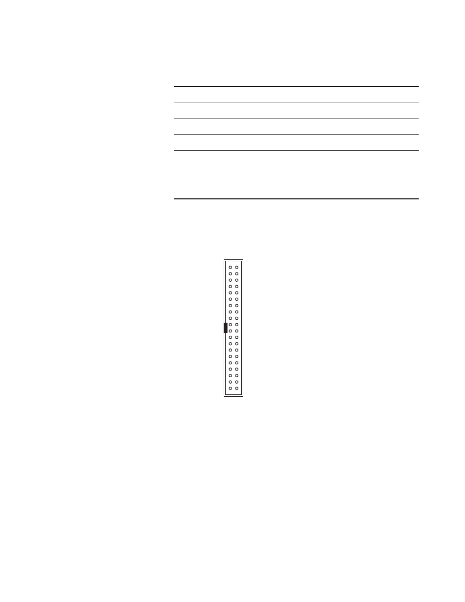
2 POWER GND
4 SIGNAL GND
6 SIGNAL GND
8 SIGNAL GND
10 SIGNAL GND
12 SIGNAL GND
14 SIGNAL GND
16 SIGNAL GND
18 SIGNAL GND
20 SIGNAL GND
22 SIGNAL GND
24 SIGNAL GND
26 SIGNAL GND
28 SIGNAL GND
30 SIGNAL GND
32 SIGNAL GND
34 SIGNAL GND
36 SIGNAL GND
38 SIGNAL GND
40 POWER GND
+5V (see note) 1
CLOCK 3
Do not connect 5
D15 7
D14 9
D13 11
D12 13
D11 15
D10 17
D9 19
D8 21
D7 23
D6 25
D5 27
D4 29
D3 31
D2 33
D1 35
D0 37
+5V 39
Figure 7.6. Forty-pin connector pinout
Note: +5V is supplied from the
logic analyzer to provide power
for analysis probes and demo
boards. DO NOT connect these
pins to a +5V supply in the
target system!