Atec Agilent-346a User Manual
Page 31
31
Designing and Probing with Target Connections
For All Agilent Logic Analyzers with 40-pin Pod Connectors
Agilent Technologies E5351A
38-Pin Adapter Cable
If the calculated electrical
length of the required routing
stub prohibits the use of the
Agilent E5339A, E5346A, or
E5385A, the Agilent E5351A
can be used with the required
isolation networks installed on
the target.
The E5351A does not have its
own internal isolation networks.
When using the E5351A, place
the SIP isolation networks,
surface mount isolation network
5062-7396, or equivalent discrete
components very near the target
component for measurement.
Ensure that the stub length
between the target component
and the isolation network is
short. The stub propagation
delay should be less than 20%
of the bus signal rise time, as
mentioned before. The transmis-
sion line from the on-board
isolation network to the Mictor
connector should be designed for
an impedance in the range of 80
to 100 ohms (closer to 100 ohms
is better). This length should not
exceed 3 to 4 inches, and all
signal line lengths should be
equal. Signal line length variation
should not cause propagation
delay variation to exceed 20 ps
between signal lines.
F
k
p
E5351A Probe
Figure 5.24. Agilent Technologies E5351A design rules
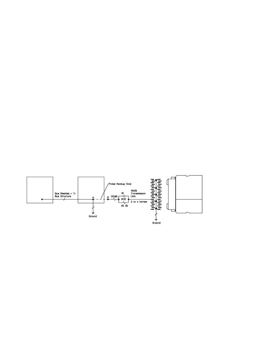
Notes on Using Discrete Components
Discrete components can be used
in the design of the RC network.
Agilent Technologies recommends
the circuit shown in Figure 5.25.
To achieve the equivalent load
shown in the figure, trace lengths
should be minimized by locating
the RC network very near the
measured node. Actual load will
be the stub length load added to
the equivalent load in the figure.