Atec Agilent-346a User Manual
Page 56
56
Designing and Probing with Target Connections
Agilent Logic Analyzers with 90-pin Pod Connectors
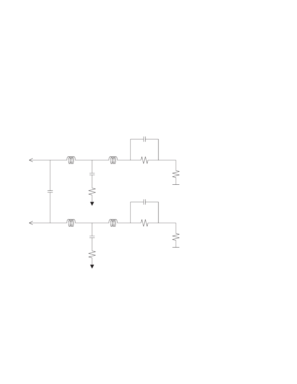
Equivalent Probe Loads
The following probe load
models are based on in-circuit
measurements made with an
Agilent 8753E 6 GHz network
analyzer and an Agilent 54750A
TDR/TDT using a 50
Ω test
fixture. The following schematic
accurately models the probe load
out to 6 GHz. PC board pads are
not included.
Cshnt1
.350 pF
Rtip1
20 K
Ω
Cshnt2
.350 pF
Rtip2
20 K
Ω
L12
1.17 nH
L22
1.17 nH
L11
0.63 nH
L21
D1
D0
0.63 nH
Rtrm1
75
Ω
C12
0.280 pF
Rgnd1
0.5
Ω
C22
0.280 pF
Rgnd2
0.5
Ω
Cm12
0.070 pF
+0.75 V
Rtrm2
75
Ω
+0.75 V
Figure 8.17. Equivalent probe load model
See also other documents in the category Atec Equipment:
- Anritsu-PIM-MW82119A (2 pages)
- Boonton-PIM31 (6 pages)
- AWT-PIM-S1L-Tetra Series (2 pages)
- AWT-PIM-S1P Series (2 pages)
- AWT-PIM-S1L Series (2 pages)
- AWT-PIM-Expandable Series (2 pages)
- AWT-PIM-Single Series (2 pages)
- CCI-PimPro (4 pages)
- JDSU-FST-2310 (10 pages)
- JDSU-T-Berd-6000 (8 pages)
- Agilent-N9912A (2 pages)
- Agilent-E5515C (4 pages)
- Agilent-E4406A (20 pages)
- Agilent-N4010A (16 pages)
- Anritsu-S412E (19 pages)
- Anritsu-S810D-S820D (2 pages)
- Anritsu-S820E (16 pages)
- Anritsu-MT8221B (24 pages)
- Anritsu-MT8221B (28 pages)
- Anritsu-S412D (16 pages)
- Anritsu-MT8222A (8 pages)
- Anritsu-MT8220T (28 pages)
- Anritsu-MT8212E-MT8213E (32 pages)
- Anritsu-S332D-31D (12 pages)
- Anritsu-MT8212A (2 pages)
- Bird-SA Series (2 pages)
- Anritsu-S331E-S332E-S361E-S362E (16 pages)
- Anritsu-S331L (12 pages)
- Advantest-Q8163 (1 page)
- Agilent-83557A-83558A (4 pages)
- Agilent-8169A (6 pages)
- Agilent-11896A (5 pages)
- Agilent-81689A_B-81649A (6 pages)
- Agilent-8163A-81634A (8 pages)
- Agilent-81624B (11 pages)
- Agilent-81618A (112 pages)
- Agilent-8703A (16 pages)
- Agilent-8156A (8 pages)
- Advanced-Fiber-Solutions-OLK51 Series (5 pages)
- Anritsu_MS9720A (12 pages)
- Anritsu-ML9001A (4 pages)
- Corning-Optivisor400 (6 pages)
- Anritsu_CMA5000a (4 pages)
- Agilent-E6008B (12 pages)
- AFL-Noyes-FLX3 (6 pages)